
ECS4510 Series Web Management Guide-R03
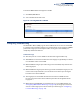
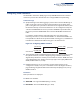
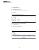
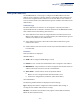
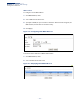
Table Of Contents
- How to Use This Guide
- Contents
- Figures
- Tables
- Getting Started
- Web Configuration
- Using the Web Interface
- Basic Management Tasks
- Displaying System Information
- Displaying Hardware/Software Versions
- Configuring Support for Jumbo Frames
- Displaying Bridge Extension Capabilities
- Managing System Files
- Setting the System Clock
- Configuring the Console Port
- Configuring Telnet Settings
- Displaying CPU Utilization
- Displaying Memory Utilization
- Stacking
- Resetting the System
- Interface Configuration
- VLAN Configuration
- Address Table Settings
- Spanning Tree Algorithm
- Congestion Control
- Class of Service
- Quality of Service
- VoIP Traffic Configuration
- Security Measures
- AAA (Authentication, Authorization and Accounting)
- Configuring User Accounts
- Web Authentication
- Network Access (MAC Address Authentication)
- Configuring HTTPS
- Configuring the Secure Shell
- Access Control Lists
- Setting a Time Range
- Showing TCAM Utilization
- Setting the ACL Name and Type
- Configuring a Standard IPv4 ACL
- Configuring an Extended IPv4 ACL
- Configuring a Standard IPv6 ACL
- Configuring an Extended IPv6 ACL
- Configuring a MAC ACL
- Configuring an ARP ACL
- Binding a Port to an Access Control List
- Configuring ACL Mirroring
- Showing ACL Hardware Counters
- ARP Inspection
- Filtering IP Addresses for Management Access
- Configuring Port Security
- Configuring 802.1X Port Authentication
- DoS Protection
- IPv4 Source Guard
- IPv6 Source Guard
- DHCP Snooping
- Basic Administration Protocols
- Configuring Event Logging
- Link Layer Discovery Protocol
- Power over Ethernet
- Simple Network Management Protocol
- Configuring Global Settings for SNMP
- Setting the Local Engine ID
- Specifying a Remote Engine ID
- Setting SNMPv3 Views
- Configuring SNMPv3 Groups
- Setting Community Access Strings
- Configuring Local SNMPv3 Users
- Configuring Remote SNMPv3 Users
- Specifying Trap Managers
- Creating SNMP Notification Logs
- Showing SNMP Statistics
- Remote Monitoring
- Switch Clustering
- Ethernet Ring Protection Switching
- Connectivity Fault Management
- Configuring Global Settings for CFM
- Configuring Interfaces for CFM
- Configuring CFM Maintenance Domains
- Configuring CFM Maintenance Associations
- Configuring Maintenance End Points
- Configuring Remote Maintenance End Points
- Transmitting Link Trace Messages
- Transmitting Loop Back Messages
- Transmitting Delay-Measure Requests
- Displaying Local MEPs
- Displaying Details for Local MEPs
- Displaying Local MIPs
- Displaying Remote MEPs
- Displaying Details for Remote MEPs
- Displaying the Link Trace Cache
- Displaying Fault Notification Settings
- Displaying Continuity Check Errors
- OAM Configuration
- UDLD Configuration
- Multicast Filtering
- Overview
- Layer 2 IGMP (Snooping and Query for IPv4)
- Configuring IGMP Snooping and Query Parameters
- Specifying Static Interfaces for a Multicast Router
- Assigning Interfaces to Multicast Services
- Setting IGMP Snooping Status per Interface
- Filtering IGMP Query Packets and Multicast Data
- Displaying Multicast Groups Discovered by IGMP Snooping
- Displaying IGMP Snooping Statistics
- Filtering and Throttling IGMP Groups
- MLD Snooping (Snooping and Query for IPv6)
- Multicast VLAN Registration for IPv4
- Multicast VLAN Registration for IPv6
- IP Configuration
- IP Services
- General IP Routing
- Unicast Routing
- Overview
- Configuring the Routing Information Protocol
- Configuring General Protocol Settings
- Clearing Entries from the Routing Table
- Specifying Network Interfaces
- Specifying Passive Interfaces
- Specifying Static Neighbors
- Configuring Route Redistribution
- Specifying an Administrative Distance
- Configuring Network Interfaces for RIP
- Displaying RIP Interface Settings
- Displaying Peer Router Information
- Resetting RIP Statistics
- Appendices
- Glossary
- Index

Chapter 5
| VLAN Configuration
Configuring VLAN Translation
– 185 –
Configuring VLAN Translation
Use the VLAN > Translation (Add) page to map VLAN IDs between the customer
and service provider for networks that do not support IEEE 802.1Q tunneling.
Command Usage
◆ QinQ tunneling uses double tagging to preserve the customer’s VLAN tags on
traffic crossing the service provider’s network. However, if any switch in the
path crossing the service provider’s network does not support this feature, then
the switches directly connected to that device can be configured to swap the
customer’s VLAN ID with the service provider’s VLAN ID for upstream traffic, or
the service provider’s VLAN ID with the customer’s VLAN ID for downstream
traffic.
For example, assume that the upstream switch does not support QinQ
tunneling. Select Port 1, and set the Old VLAN to 10 and the New VLAN to 100
to map VLAN 10 to VLAN 100 for upstream traffic entering port 1, and VLAN 100
to VLAN 10 for downstream traffic leaving port 1 as shown below.
Figure 96: Configuring VLAN Translation
◆ The maximum number of VLAN translation entries is 8 per port, and up to 96 for
the system. However, note that configuring a large number of entries may
degrade the performance of other processes that also use the TCAM, such as IP
Source Guard filter rules, Quality of Service (QoS) processes, QinQ, MAC-based
VLANs, VLAN translation, or traps.
◆ If VLAN translation is set on an interface, and the same interface is also
configured as a QinQ access port on the VLAN > Tunnel (Configure Interface)
page, VLAN tag assignments will be determined by the QinQ process, not by
VLAN translation.
Parameters
These parameters are displayed:
◆ Port – Port identifier.
◆ Old VLAN – The original VLAN ID. (Range: 1-4093)
◆ New VLAN – The new VLAN ID. (Range: 1-4093)
12
(VLAN 10) (VLAN 100)
(VLAN 100)
(VLAN 10)
upstream
downstream