
ECS4510 Series Web Management Guide-R03
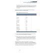
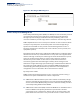
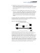
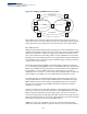
Table Of Contents
- How to Use This Guide
- Contents
- Figures
- Tables
- Getting Started
- Web Configuration
- Using the Web Interface
- Basic Management Tasks
- Displaying System Information
- Displaying Hardware/Software Versions
- Configuring Support for Jumbo Frames
- Displaying Bridge Extension Capabilities
- Managing System Files
- Setting the System Clock
- Configuring the Console Port
- Configuring Telnet Settings
- Displaying CPU Utilization
- Displaying Memory Utilization
- Stacking
- Resetting the System
- Interface Configuration
- VLAN Configuration
- Address Table Settings
- Spanning Tree Algorithm
- Congestion Control
- Class of Service
- Quality of Service
- VoIP Traffic Configuration
- Security Measures
- AAA (Authentication, Authorization and Accounting)
- Configuring User Accounts
- Web Authentication
- Network Access (MAC Address Authentication)
- Configuring HTTPS
- Configuring the Secure Shell
- Access Control Lists
- Setting a Time Range
- Showing TCAM Utilization
- Setting the ACL Name and Type
- Configuring a Standard IPv4 ACL
- Configuring an Extended IPv4 ACL
- Configuring a Standard IPv6 ACL
- Configuring an Extended IPv6 ACL
- Configuring a MAC ACL
- Configuring an ARP ACL
- Binding a Port to an Access Control List
- Configuring ACL Mirroring
- Showing ACL Hardware Counters
- ARP Inspection
- Filtering IP Addresses for Management Access
- Configuring Port Security
- Configuring 802.1X Port Authentication
- DoS Protection
- IPv4 Source Guard
- IPv6 Source Guard
- DHCP Snooping
- Basic Administration Protocols
- Configuring Event Logging
- Link Layer Discovery Protocol
- Power over Ethernet
- Simple Network Management Protocol
- Configuring Global Settings for SNMP
- Setting the Local Engine ID
- Specifying a Remote Engine ID
- Setting SNMPv3 Views
- Configuring SNMPv3 Groups
- Setting Community Access Strings
- Configuring Local SNMPv3 Users
- Configuring Remote SNMPv3 Users
- Specifying Trap Managers
- Creating SNMP Notification Logs
- Showing SNMP Statistics
- Remote Monitoring
- Switch Clustering
- Ethernet Ring Protection Switching
- Connectivity Fault Management
- Configuring Global Settings for CFM
- Configuring Interfaces for CFM
- Configuring CFM Maintenance Domains
- Configuring CFM Maintenance Associations
- Configuring Maintenance End Points
- Configuring Remote Maintenance End Points
- Transmitting Link Trace Messages
- Transmitting Loop Back Messages
- Transmitting Delay-Measure Requests
- Displaying Local MEPs
- Displaying Details for Local MEPs
- Displaying Local MIPs
- Displaying Remote MEPs
- Displaying Details for Remote MEPs
- Displaying the Link Trace Cache
- Displaying Fault Notification Settings
- Displaying Continuity Check Errors
- OAM Configuration
- UDLD Configuration
- Multicast Filtering
- Overview
- Layer 2 IGMP (Snooping and Query for IPv4)
- Configuring IGMP Snooping and Query Parameters
- Specifying Static Interfaces for a Multicast Router
- Assigning Interfaces to Multicast Services
- Setting IGMP Snooping Status per Interface
- Filtering IGMP Query Packets and Multicast Data
- Displaying Multicast Groups Discovered by IGMP Snooping
- Displaying IGMP Snooping Statistics
- Filtering and Throttling IGMP Groups
- MLD Snooping (Snooping and Query for IPv6)
- Multicast VLAN Registration for IPv4
- Multicast VLAN Registration for IPv6
- IP Configuration
- IP Services
- General IP Routing
- Unicast Routing
- Overview
- Configuring the Routing Information Protocol
- Configuring General Protocol Settings
- Clearing Entries from the Routing Table
- Specifying Network Interfaces
- Specifying Passive Interfaces
- Specifying Static Neighbors
- Configuring Route Redistribution
- Specifying an Administrative Distance
- Configuring Network Interfaces for RIP
- Displaying RIP Interface Settings
- Displaying Peer Router Information
- Resetting RIP Statistics
- Appendices
- Glossary
- Index

Chapter 13
| Basic Administration Protocols
Ethernet Ring Protection Switching
– 474 –
ERPS Forced and
Manual Mode
Operations
Use the Administration > ERPS (Configure Operation) page to block a ring port
using Forced Switch or Manual Switch commands.
Parameters
These parameters are displayed:
◆ Domain Name – Name of a configured ERPS ring.
◆ Operation – Specifies a Forced Switch (FS) or Manual Switch (MS) operation on
the east or west ring port.
■
Forced Switch – Blocks specified ring port. (Options: West or East)
■
A ring with no pending request has a logical topology with the traffic
channel blocked at the RPL and unblocked on all other ring links. In this
situation, the FS command triggers protection switching as follows:
a. The ring node where an FS command was issued blocks the traffic
channel and R-APS channel on the ring port to which the
command was issued, and unblocks the other ring port.
b. The ring node where the FS command was issued transmits R-APS
messages indicating FS over both ring ports. R-APS (FS) messages
are continuously transmitted by this ring node while the local FS
command is the ring node’s highest priority command (see
Table 30 on page 475). The R-APS (FS) message informs other ring
nodes of the FS command and that the traffic channel is blocked on
one ring port.
c. A ring node accepting an R-APS (FS) message, without any local
higher priority requests unblocks any blocked ring port. This action
subsequently unblocks the traffic channel over the RPL.
d. The ring node accepting an R-APS (FS) message, without any local
higher priority requests stops transmission of R-APS messages.
e. The ring node receiving an R-APS (FS) message flushes its FDB.
■
Protection switching on a forced switch request is completed when the
above actions are performed by each ring node. At this point, traffic
flows around the ring are resumed. From this point on the following
rules apply regarding processing of further forced switch commands:
■
While an existing forced switch request is present in a ring, any new
forced switch request is accepted, except on a ring node having a
prior local forced switch request. The ring nodes where further
forced switch commands are issued block the traffic channel and R-
APS channel on the ring port at which the forced switch was issued.
The ring node where the forced switch command was issued
transmits an R-APS message over both ring ports indicating FS. R-
APS (FS) messages are continuously transmitted by this ring node
while the local FS command is the ring node’s highest priority