
ECS4510 Series Web Management Guide-R03


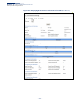
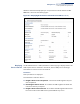


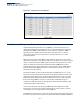
Table Of Contents
- How to Use This Guide
- Contents
- Figures
- Tables
- Getting Started
- Web Configuration
- Using the Web Interface
- Basic Management Tasks
- Displaying System Information
- Displaying Hardware/Software Versions
- Configuring Support for Jumbo Frames
- Displaying Bridge Extension Capabilities
- Managing System Files
- Setting the System Clock
- Configuring the Console Port
- Configuring Telnet Settings
- Displaying CPU Utilization
- Displaying Memory Utilization
- Stacking
- Resetting the System
- Interface Configuration
- VLAN Configuration
- Address Table Settings
- Spanning Tree Algorithm
- Congestion Control
- Class of Service
- Quality of Service
- VoIP Traffic Configuration
- Security Measures
- AAA (Authentication, Authorization and Accounting)
- Configuring User Accounts
- Web Authentication
- Network Access (MAC Address Authentication)
- Configuring HTTPS
- Configuring the Secure Shell
- Access Control Lists
- Setting a Time Range
- Showing TCAM Utilization
- Setting the ACL Name and Type
- Configuring a Standard IPv4 ACL
- Configuring an Extended IPv4 ACL
- Configuring a Standard IPv6 ACL
- Configuring an Extended IPv6 ACL
- Configuring a MAC ACL
- Configuring an ARP ACL
- Binding a Port to an Access Control List
- Configuring ACL Mirroring
- Showing ACL Hardware Counters
- ARP Inspection
- Filtering IP Addresses for Management Access
- Configuring Port Security
- Configuring 802.1X Port Authentication
- DoS Protection
- IPv4 Source Guard
- IPv6 Source Guard
- DHCP Snooping
- Basic Administration Protocols
- Configuring Event Logging
- Link Layer Discovery Protocol
- Power over Ethernet
- Simple Network Management Protocol
- Configuring Global Settings for SNMP
- Setting the Local Engine ID
- Specifying a Remote Engine ID
- Setting SNMPv3 Views
- Configuring SNMPv3 Groups
- Setting Community Access Strings
- Configuring Local SNMPv3 Users
- Configuring Remote SNMPv3 Users
- Specifying Trap Managers
- Creating SNMP Notification Logs
- Showing SNMP Statistics
- Remote Monitoring
- Switch Clustering
- Ethernet Ring Protection Switching
- Connectivity Fault Management
- Configuring Global Settings for CFM
- Configuring Interfaces for CFM
- Configuring CFM Maintenance Domains
- Configuring CFM Maintenance Associations
- Configuring Maintenance End Points
- Configuring Remote Maintenance End Points
- Transmitting Link Trace Messages
- Transmitting Loop Back Messages
- Transmitting Delay-Measure Requests
- Displaying Local MEPs
- Displaying Details for Local MEPs
- Displaying Local MIPs
- Displaying Remote MEPs
- Displaying Details for Remote MEPs
- Displaying the Link Trace Cache
- Displaying Fault Notification Settings
- Displaying Continuity Check Errors
- OAM Configuration
- UDLD Configuration
- Multicast Filtering
- Overview
- Layer 2 IGMP (Snooping and Query for IPv4)
- Configuring IGMP Snooping and Query Parameters
- Specifying Static Interfaces for a Multicast Router
- Assigning Interfaces to Multicast Services
- Setting IGMP Snooping Status per Interface
- Filtering IGMP Query Packets and Multicast Data
- Displaying Multicast Groups Discovered by IGMP Snooping
- Displaying IGMP Snooping Statistics
- Filtering and Throttling IGMP Groups
- MLD Snooping (Snooping and Query for IPv6)
- Multicast VLAN Registration for IPv4
- Multicast VLAN Registration for IPv6
- IP Configuration
- IP Services
- General IP Routing
- Unicast Routing
- Overview
- Configuring the Routing Information Protocol
- Configuring General Protocol Settings
- Clearing Entries from the Routing Table
- Specifying Network Interfaces
- Specifying Passive Interfaces
- Specifying Static Neighbors
- Configuring Route Redistribution
- Specifying an Administrative Distance
- Configuring Network Interfaces for RIP
- Displaying RIP Interface Settings
- Displaying Peer Router Information
- Resetting RIP Statistics
- Appendices
- Glossary
- Index

Chapter 13
| Basic Administration Protocols
Power over Ethernet
– 408 –
Ports can be set to one of three power priority levels, critical, high, or low. To control
the power supply within the switch’s budget, ports set at critical to high priority
have power enabled in preference to those ports set at low priority. For example,
when a device connected to a port is set to critical priority, the switch supplies the
required power, if necessary by denying power to ports set for a lower priority
during bootup.
Note:
For more information on using the PoE provided by this switch refer to the
Installation Guide.
Setting the Port
PoE Power Budget
Use the Administration > PoE > PSE page to set the maximum power provided to a
port.
Command Usage
◆ This switch supports both the IEEE 802.3af PoE and IEEE 802.3at-2009 PoE Plus
standards. To ensure that the correct power is supplied to powered devices
(PD) compliant with these standards, the first detection pulse from the switch is
based on 802.3af to which the 802.3af PDs will respond normally. It then sends
a second PoE Plus pulse that causes an 802.3at PD to respond as a Class 4
device and draw Class 4 current. Afterwards, the switch exchanges information
with the PD such as duty-cycle, peak and average power needs.
◆ All the RJ-45 ports support both the IEEE 802.3af and IEEE 802.3at standards.
■
For the ECS4620-28P, the total PoE power delivered by all ports cannot
exceed the maximum power budget of 410W. This means that up to 13
ports can supply a maximum 30W of power simultaneously to connected
devices (802.3at), or up to 24 ports can supply up to 15.4W (802.3af).
■
For the ECS4620-52P, the total PoE power delivered by all ports cannot
exceed the maximum power budget of 730W when power is provided from
the RPS. This means that up to 23 ports can supply a maximum 30W of
power simultaneously to connected devices (802.3at), or up to 48 ports can
supply up to 15.4W (802.3af).
◆ If a device is connected to a switch port and the switch detects that it requires
more than the power budget set for the port or to the overall switch, no power
is supplied to the device (i.e., port power remains off).
◆ If the power demand from devices connected to all switch ports exceeds the
power budget set for the switch, the port power priority settings are used to
control the supplied power. For example:
■
If a device is connected to a low-priority port and causes the switch to
exceed its budget, power to this port is not turned on.
■
If a device is connected to a critical or high-priority port and would cause
the switch to exceed its power budget as determined during bootup,