
Web Management Guide-R03
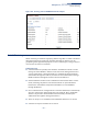

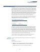
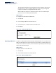
Table Of Contents
- How to Use This Guide
- Contents
- Figures
- Tables
- Getting Started
- Web Configuration
- Basic Management Tasks
- Displaying System Information
- Displaying Hardware/Software Versions
- Configuring Support for Jumbo Frames
- Displaying Bridge Extension Capabilities
- Managing System Files
- Setting the System Clock
- Configuring the Console Port
- Configuring Telnet Settings
- Displaying CPU Utilization
- Displaying Memory Utilization
- Resetting the System
- Interface Configuration
- VLAN Configuration
- Address Table Settings
- Spanning Tree Algorithm
- Congestion Control
- Class of Service
- Quality of Service
- VoIP Traffic Configuration
- Security Measures
- AAA Authorization and Accounting
- Configuring User Accounts
- Web Authentication
- Network Access (MAC Address Authentication)
- Configuring HTTPS
- Configuring the Secure Shell
- Access Control Lists
- Setting A Time Range
- Showing TCAM Utilization
- Setting the ACL Name and Type
- Configuring a Standard IPv4 ACL
- Configuring an Extended IPv4 ACL
- Configuring a Standard IPv6 ACL
- Configuring an Extended IPv6 ACL
- Configuring a MAC ACL
- Configuring an ARP ACL
- Binding a Port to an Access Control List
- Configuring ACL Mirroring
- Showing ACL Hardware Counters
- ARP Inspection
- Filtering IP Addresses for Management Access
- Configuring Port Security
- Configuring 802.1X Port Authentication
- DoS Protection
- IP Source Guard
- DHCP Snooping
- Basic Administration Protocols
- Configuring Event Logging
- Link Layer Discovery Protocol
- Power over Ethernet
- Simple Network Management Protocol
- Configuring Global Settings for SNMP
- Setting the Local Engine ID
- Specifying a Remote Engine ID
- Setting SNMPv3 Views
- Configuring SNMPv3 Groups
- Setting Community Access Strings
- Configuring Local SNMPv3 Users
- Configuring Remote SNMPv3 Users
- Specifying Trap Managers
- Creating SNMP Notification Logs
- Showing SNMP Statistics
- Remote Monitoring
- Switch Clustering
- IP Configuration
- IP Services
- Multicast Filtering
- Overview
- Layer 2 IGMP (Snooping and Query)
- Configuring IGMP Snooping and Query Parameters
- Specifying Static Interfaces for a Multicast Router
- Assigning Interfaces to Multicast Services
- Setting IGMP Snooping Status per Interface
- Filtering Multicast Data at Interfaces
- Displaying Multicast Groups Discovered by IGMP Snooping
- Displaying IGMP Snooping Statistics
- Filtering and Throttling IGMP Groups
- MLD Snooping (Snooping and Query for IPv6)
- Multicast VLAN Registration
- Basic Management Tasks
- Appendices
- Glossary
- Index

Chapter 13
| Basic Administration Protocols
Switch Clustering
– 422 –
◆ After the Commander and Members have been configured, any switch in the
cluster can be managed from the web agent by choosing the desired Member
ID from the Show Member page.
Configuring General
Settings for Clusters
Use the Administration > Cluster (Configure Global) page to create a switch cluster.
Command Usage
First be sure that clustering is enabled on the switch (the default is disabled), then
set the switch as a Cluster Commander. Set a Cluster IP Pool that does not conflict
with the network IP subnet. Cluster IP addresses are assigned to switches when
they become Members and are used for communication between Member
switches and the Commander.
Parameters
These parameters are displayed:
◆ Cluster Status – Enables or disables clustering on the switch. (Default:
Disabled)
◆ Commander Status – Enables or disables the switch as a cluster Commander.
(Default: Disabled)
◆ IP Pool – An “internal” IP address pool that is used to assign IP addresses to
Member switches in the cluster. Internal cluster IP addresses are in the form
10.x.x.member-ID. Only the base IP address of the pool needs to be set since
Member IDs can only be between 1 and 36. Note that you cannot change the
cluster IP pool when the switch is currently in Commander mode. Commander
mode must first be disabled. (Default: 10.254.254.1)
◆ Role – Indicates the current role of the switch in the cluster; either Commander,
Member, or Candidate. (Default: Candidate)
◆ Number of Members – The current number of Member switches in the cluster.
◆ Number of Candidates – The current number of Candidate switches
discovered in the network that are available to become Members.
Web Interface
To configure a switch cluster:
1. Click Administration, Cluster.
2. Select Configure Global from the Step list.
3. Set the required attributes for a Commander or a managed candidate.
4. Click Apply