
ECS4210-12T_Installation Guide
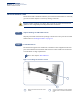
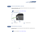
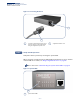
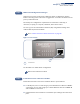
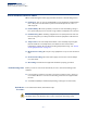
Table Of Contents
- Front Page - ECS4210-12T Installation Guide
- How to Use This Guide
- Contents
- Figures
- Tables
- Switch Description
- Installation Overview
- Switch Chassis
- Power and Grounding
- Port Connections
- Switch Management
- Troubleshooting
- Index
- Back Page

Chapter 2
| Installation Overview
Switch Installation Tasks
– 16 –
Figure 5: Connecting AC Power
Verify Switch Operation
Verify basic switch operation by checking the system LEDs.
When operating normally, the Pwr and Diag LED should both be on green. If either
of these LEDs are on amber, see “Diagnosing LED Indicators” on page 44.
Go to the section “Understanding the System Status LEDs” on page 40
Figure 6: System LEDs
Connect an external AC power source
to the AC power socket of the switch
using the supplied AC power cord.
Supplied AC Power cord.
2
1
1
2
Task 5
System Status LEDs.
1
1