
ECS4210-12T_Installation Guide


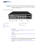
Table Of Contents
- Front Page - ECS4210-12T Installation Guide
- How to Use This Guide
- Contents
- Figures
- Tables
- Switch Description
- Installation Overview
- Switch Chassis
- Power and Grounding
- Port Connections
- Switch Management
- Troubleshooting
- Index
- Back Page

Chapter 1
| Switch Description
Overview
– 10 –
Key Hardware
Components
The switch consists of several key hardware components. This manual describes
each specific component, or related components, together with their installation
requirements and procedures in each chapter. To understand each component in
detail, refer to the relevant section.
Figure 1: Front Panel ECS4210-12T
System LEDs
For information on system status LED indicators, see “Understanding the System
Status LEDs” on page 40.
Port LEDs
For information on port status LED indicators, see “Understanding the Port Status
LEDs” on page 31.
Console Port
The RJ-45 connector on the front panel right side that is labeled “Console” provides
an out-of-band serial connection to a terminal or a PC running terminal emulation
software. The port can be used for performing switch monitoring and
configuration. For more information, see “How to Connect to the Console Port” on
page 40.
System LEDs 1000BASE-T RJ-45 Ports
Port LEDs Gigabit SFP Slots
RJ-45 Console Port
1 2 3 4 5
1
4
2
5
3