
Web Management Guide-R03
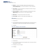
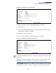
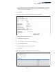
Table Of Contents
- How to Use This Guide
- Contents
- Figures
- Tables
- Getting Started
- Web Configuration
- Basic Management Tasks
- Displaying System Information
- Displaying Hardware/Software Versions
- Configuring Support for Jumbo Frames
- Displaying Bridge Extension Capabilities
- Managing System Files
- Setting the System Clock
- Configuring the Console Port
- Configuring Telnet Settings
- Displaying CPU Utilization
- Displaying Memory Utilization
- Resetting the System
- Interface Configuration
- VLAN Configuration
- Address Table Settings
- Spanning Tree Algorithm
- Congestion Control
- Class of Service
- Quality of Service
- VoIP Traffic Configuration
- Security Measures
- AAA Authorization and Accounting
- Configuring User Accounts
- Web Authentication
- Network Access (MAC Address Authentication)
- Configuring HTTPS
- Configuring the Secure Shell
- Access Control Lists
- Setting A Time Range
- Showing TCAM Utilization
- Setting the ACL Name and Type
- Configuring a Standard IPv4 ACL
- Configuring an Extended IPv4 ACL
- Configuring a Standard IPv6 ACL
- Configuring an Extended IPv6 ACL
- Configuring a MAC ACL
- Configuring an ARP ACL
- Binding a Port to an Access Control List
- Configuring ACL Mirroring
- Showing ACL Hardware Counters
- ARP Inspection
- Filtering IP Addresses for Management Access
- Configuring Port Security
- Configuring 802.1X Port Authentication
- DoS Protection
- IP Source Guard
- DHCP Snooping
- Basic Administration Protocols
- Configuring Event Logging
- Link Layer Discovery Protocol
- Power over Ethernet
- Simple Network Management Protocol
- Configuring Global Settings for SNMP
- Setting the Local Engine ID
- Specifying a Remote Engine ID
- Setting SNMPv3 Views
- Configuring SNMPv3 Groups
- Setting Community Access Strings
- Configuring Local SNMPv3 Users
- Configuring Remote SNMPv3 Users
- Specifying Trap Managers
- Creating SNMP Notification Logs
- Showing SNMP Statistics
- Remote Monitoring
- Switch Clustering
- IP Configuration
- IP Services
- Multicast Filtering
- Overview
- Layer 2 IGMP (Snooping and Query)
- Configuring IGMP Snooping and Query Parameters
- Specifying Static Interfaces for a Multicast Router
- Assigning Interfaces to Multicast Services
- Setting IGMP Snooping Status per Interface
- Filtering Multicast Data at Interfaces
- Displaying Multicast Groups Discovered by IGMP Snooping
- Displaying IGMP Snooping Statistics
- Filtering and Throttling IGMP Groups
- MLD Snooping (Snooping and Query for IPv6)
- Multicast VLAN Registration
- Basic Management Tasks
- Appendices
- Glossary
- Index

Chapter 14
| IP Configuration
Setting the Switch’s IP Address (IP Version 4)
– 431 –
Setting the Switch’s IP Address (IP Version 4)
Use the System > IP page to configure an IPv4 address for management access over
the network. This switch supports both IPv4 and IPv6, and can be managed
through either of these address types. For information on configuring the switch
with an IPv6 address, see “Setting the Switch’s IP Address (IP Version 6)” on
page 434.
You can direct the device to obtain an address through Auto IP, from a BOOTP or
DHCP server, or manually configure a static IP address. Valid IP addresses consist of
four decimal numbers, 0 to 255, separated by periods. Anything other than this
format will not be accepted.
To configure an address compatible with your network, you may need to change
the switch’s default settings. You may also need to a establish a default gateway
between the switch and management stations that exist on another network
segment.
Parameters
These parameters are displayed:
◆ Management VLAN – ID of the configured VLAN (1-4094). By default, all ports
on the switch are members of VLAN 1. However, the management station can
be attached to a port belonging to any VLAN, as long as that VLAN has been
assigned an IP address.
◆ IP Address Mode – Specifies whether IP functionality is enabled via manual
configuration (Static), Auto IP, Dynamic Host Configuration Protocol (DHCP), or
Boot Protocol (BOOTP). (Default: DHCP)
■
If DHCP/BOOTP is enabled, IP will not function until a reply has been
received from the server. Requests will be broadcast periodically by the
switch for an IP address. DHCP/BOOTP responses can include the IP
address, subnet mask, and default gateway.
■
If IP address mode is set to Auto IP, the switch randomly selects an IPv4 link-
local address from 169.254.0.1~169.254.255.254. Before starting to use it,
the switch tests to see if the address is already in use.
Conflict detection is done using ARP probes. The switch waits a predefined
number of seconds after the transmission of the last ARP probe. If no
conflicting ARP Reply or ARP Probe has been received, then the switch has
successfully claimed the desired IPv4 link-local address.
When a network interface transitions from inactive to active state, the
switch does not know what IPv4 link-local addresses are currently in use on
that link since the point of attachment may have changed or the network
interface may have been inactive when a conflicting address was claimed.
In this case, the switch again starts sending ARP probes to see if the
previously selecting address has been claimed by another device on the
network.