
Web Management Guide-R01
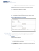
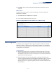
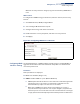
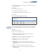
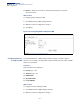
Table Of Contents
- How to Use This Guide
- Contents
- Figures
- Tables
- Getting Started
- Web Configuration
- Using the Web Interface
- Basic Management Tasks
- Displaying System Information
- Displaying Hardware/Software Versions
- Configuring Support for Jumbo Frames
- Displaying Bridge Extension Capabilities
- Managing System Files
- Setting the System Clock
- Configuring the Console Port
- Configuring Telnet Settings
- Displaying CPU Utilization
- Configuring CPU Guard
- Displaying Memory Utilization
- Resetting the System
- Interface Configuration
- VLAN Configuration
- Address Table Settings
- Spanning Tree Algorithm
- Congestion Control
- Class of Service
- Quality of Service
- VoIP Traffic Configuration
- Security Measures
- AAA (Authentication, Authorization and Accounting)
- Configuring User Accounts
- Web Authentication
- Network Access (MAC Address Authentication)
- Configuring HTTPS
- Configuring the Secure Shell
- Access Control Lists
- Filtering IP Addresses for Management Access
- Configuring Port Security
- Configuring 802.1X Port Authentication
- DoS Protection
- DHCP Snooping
- DHCPv6 Snooping
- ND Snooping
- IPv4 Source Guard
- IPv6 Source Guard
- ARP Inspection
- Application Filter
- Basic Administration Protocols
- Configuring Event Logging
- Link Layer Discovery Protocol
- Simple Network Management Protocol
- Configuring Global Settings for SNMP
- Setting Community Access Strings
- Setting the Local Engine ID
- Specifying a Remote Engine ID
- Setting SNMPv3 Views
- Configuring SNMPv3 Groups
- Configuring Local SNMPv3 Users
- Configuring Remote SNMPv3 Users
- Specifying Trap Managers
- Creating SNMP Notification Logs
- Showing SNMP Statistics
- Remote Monitoring
- Switch Clustering
- Setting a Time Range
- Ethernet Ring Protection Switching
- OAM Configuration
- UDLD Configuration
- LBD Configuration
- Multicast Filtering
- Overview
- Layer 2 IGMP (Snooping and Query for IPv4)
- Configuring IGMP Snooping and Query Parameters
- Specifying Static Interfaces for a Multicast Router
- Assigning Interfaces to Multicast Services
- Setting IGMP Snooping Status per Interface
- Filtering IGMP Packets on an Interface
- Displaying Multicast Groups Discovered by IGMP Snooping
- Displaying IGMP Snooping Statistics
- Filtering and Throttling IGMP Groups
- MLD Snooping (Snooping and Query for IPv6)
- Configuring MLD Snooping and Query Parameters
- Setting Immediate Leave Status for MLD Snooping per Interface
- Specifying Static Interfaces for an IPv6 Multicast Router
- Assigning Interfaces to IPv6 Multicast Services
- Filtering MLD Query Packets on an Interface
- Showing MLD Snooping Groups and Source List
- Displaying MLD Snooping Statistics
- Filtering and Throttling MLD Groups
- Multicast VLAN Registration for IPv4
- IP Tools
- IP Configuration
- General IP Routing
- IP Services
- Appendices

Chapter 13
| Basic Administration Protocols
UDLD Configuration
– 504 –
◆ When a loopback event is detected on an interface or when a interface is
released from a shutdown state caused by a loopback event, a trap message is
sent and the event recorded in the system log.
◆ Loopback detection must be enabled both globally and on an interface for
loopback detection to take effect.
Configuring UDLD
Protocol Intervals
Use the Administration > UDLD > Configure Global page to configure the
UniDirectional Link Detection message probe interval, detection interval, and
recovery interval.
Parameters
These parameters are displayed:
◆ Message Interval – Configures the message interval between UDLD probe
messages for ports in the advertisement phase and determined to be
bidirectional. (Range: 7-90 seconds; Default: 15 seconds)
UDLD probe messages are sent after linkup or detection phases. During the
detection phase, messages are exchanged at the maximum rate of one per
second. After that, if the protocol reaches a stable state and determines that the
link is bidirectional, the message interval is increased to a configurable value
based on a curve known as M1(t), a time-based function described in RFC 5171.
If the link is deemed anything other than bidirectional at the end of the
detection phase, this curve becomes a flat line with a fixed value of Mfast (7
seconds).
If the link is instead deemed bidirectional, the curve will use Mfast for the first
four subsequent message transmissions and then transition to an Mslow value
for all other steady-state transmissions. Mslow is the value configured by this
command.
◆ Detection Interval – Sets the amount of time the switch remains in detection
state after discovering a neighbor. (Range: 5-255 seconds; Default: 5 seconds)
When a neighbor device is discovered by UDLD, the switch enters “detection
state” and remains in this state for specified detection-interval. After the
detection-interval expires, the switch tries to decide whether or the link is
unidirectional based on the information collected during the “detection state.”
◆ Recovery Status – Configures the switch to automatically recover from UDLD
disabled port state after a period specified by the Recovery Interval. (Default:
Disabled)
When automatic recovery state is changed, any ports shut down by
UDLD will be reset.
◆
Recovery Interval – Specifies the period after which to automatically recover
from UDLD disabled port state. (Range: 30-86400 seconds; Default: 300
seconds)