
Web Management Guide-R01
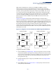
Table Of Contents
- How to Use This Guide
- Contents
- Figures
- Tables
- Getting Started
- Web Configuration
- Using the Web Interface
- Basic Management Tasks
- Displaying System Information
- Displaying Hardware/Software Versions
- Configuring Support for Jumbo Frames
- Displaying Bridge Extension Capabilities
- Managing System Files
- Setting the System Clock
- Configuring the Console Port
- Configuring Telnet Settings
- Displaying CPU Utilization
- Configuring CPU Guard
- Displaying Memory Utilization
- Resetting the System
- Interface Configuration
- VLAN Configuration
- Address Table Settings
- Spanning Tree Algorithm
- Congestion Control
- Class of Service
- Quality of Service
- VoIP Traffic Configuration
- Security Measures
- AAA (Authentication, Authorization and Accounting)
- Configuring User Accounts
- Web Authentication
- Network Access (MAC Address Authentication)
- Configuring HTTPS
- Configuring the Secure Shell
- Access Control Lists
- Filtering IP Addresses for Management Access
- Configuring Port Security
- Configuring 802.1X Port Authentication
- DoS Protection
- DHCP Snooping
- DHCPv6 Snooping
- ND Snooping
- IPv4 Source Guard
- IPv6 Source Guard
- ARP Inspection
- Application Filter
- Basic Administration Protocols
- Configuring Event Logging
- Link Layer Discovery Protocol
- Simple Network Management Protocol
- Configuring Global Settings for SNMP
- Setting Community Access Strings
- Setting the Local Engine ID
- Specifying a Remote Engine ID
- Setting SNMPv3 Views
- Configuring SNMPv3 Groups
- Configuring Local SNMPv3 Users
- Configuring Remote SNMPv3 Users
- Specifying Trap Managers
- Creating SNMP Notification Logs
- Showing SNMP Statistics
- Remote Monitoring
- Switch Clustering
- Setting a Time Range
- Ethernet Ring Protection Switching
- OAM Configuration
- UDLD Configuration
- LBD Configuration
- Multicast Filtering
- Overview
- Layer 2 IGMP (Snooping and Query for IPv4)
- Configuring IGMP Snooping and Query Parameters
- Specifying Static Interfaces for a Multicast Router
- Assigning Interfaces to Multicast Services
- Setting IGMP Snooping Status per Interface
- Filtering IGMP Packets on an Interface
- Displaying Multicast Groups Discovered by IGMP Snooping
- Displaying IGMP Snooping Statistics
- Filtering and Throttling IGMP Groups
- MLD Snooping (Snooping and Query for IPv6)
- Configuring MLD Snooping and Query Parameters
- Setting Immediate Leave Status for MLD Snooping per Interface
- Specifying Static Interfaces for an IPv6 Multicast Router
- Assigning Interfaces to IPv6 Multicast Services
- Filtering MLD Query Packets on an Interface
- Showing MLD Snooping Groups and Source List
- Displaying MLD Snooping Statistics
- Filtering and Throttling MLD Groups
- Multicast VLAN Registration for IPv4
- IP Tools
- IP Configuration
- General IP Routing
- IP Services
- Appendices

Chapter 13
| Basic Administration Protocols
Ethernet Ring Protection Switching
– 472 –
4. Configure the RPL owner (Configure Instance – Configure Details): Configure
one node in the ring as the Ring Protection Link (RPL) owner. When this switch
is configured as the RPL owner, the west ring port is set as being connected to
the RPL. Under normal operations (Idle state), the RPL is blocked to ensure that
a loop cannot form in the ring. If a signal failure brings down any other link in
the ring, the RPL will be unblocked (Protection state) to ensure proper
connectivity among all ring nodes until the failure is recovered.
5. Configure ERPS timers (Configure Instance – Configure Details): Set the Guard
timer to prevent ring nodes from receiving outdated R-APS messages, the
Hold-off timer to filter out intermittent link faults, and the WTR timer to verify
that the ring has stabilized before blocking the RPL after recovery from a signal
failure.
6. Configure the ERPS Control VLAN (Configure Instance – Configure Details):
Specify the Control VLAN (CVLAN) used to pass R-APS ring maintenance
commands. The CVLAN must NOT be configured with an IP address. In addition,
only ring ports may be added to the CVLAN (prior to configuring the VLAN as a
CVLAN). No other ports can be members of this VLAN (once set as a CVLAN).
Also, the ring ports of the CVLAN must be tagged. Failure to observe these
restrictions can result in a loop in the network.
7. Select the Inclusion VLAN groups (Configure Instance – Configure Details):
Select the ERPS VLAN groups to assign to the instances.
8. Enable ERPS (Configure Global): Before enabling a ring and instance as
described in the next steps, first globally enable ERPS on the switch. If ERPS has
not yet been enabled or has been disabled, no ERPS rings will work.
9. Enable an ERPS ring (Configure Ring – Add/Modify): Before an ERPS instance
can work, the physical ring must be enabled.
10. Enable an ERPS instance (Configure Instance – Configure Details): Before an
ERPS instance can work, it must be enabled. When configuration is completed
and the instance enabled, R-APS messages will start flowing in the control
VLAN, and normal traffic will begin to flow in the data VLANs. A ring can be
stopped by disabling the Status on any node.
11. Display ERPS status information (Configure Instance – Show): Display ERPS
status information for all configured rings.
Configuration Limitations for ERPS
The following configuration limitations apply to ERPS:
◆ Ring ports cannot be a member of a trunk, nor an LACP-enabled port.
◆ Dynamic VLANs are not supported as protected data ports.
◆ Exclusive use of STP or ERPS on any port.