
Web Management Guide-R01
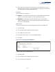
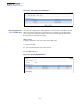
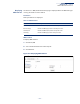

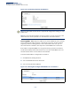
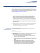
Table Of Contents
- How to Use This Guide
- Contents
- Figures
- Tables
- Getting Started
- Web Configuration
- Using the Web Interface
- Basic Management Tasks
- Displaying System Information
- Displaying Hardware/Software Versions
- Configuring Support for Jumbo Frames
- Displaying Bridge Extension Capabilities
- Managing System Files
- Setting the System Clock
- Configuring the Console Port
- Configuring Telnet Settings
- Displaying CPU Utilization
- Configuring CPU Guard
- Displaying Memory Utilization
- Resetting the System
- Interface Configuration
- VLAN Configuration
- Address Table Settings
- Spanning Tree Algorithm
- Congestion Control
- Class of Service
- Quality of Service
- VoIP Traffic Configuration
- Security Measures
- AAA (Authentication, Authorization and Accounting)
- Configuring User Accounts
- Web Authentication
- Network Access (MAC Address Authentication)
- Configuring HTTPS
- Configuring the Secure Shell
- Access Control Lists
- Filtering IP Addresses for Management Access
- Configuring Port Security
- Configuring 802.1X Port Authentication
- DoS Protection
- DHCP Snooping
- DHCPv6 Snooping
- ND Snooping
- IPv4 Source Guard
- IPv6 Source Guard
- ARP Inspection
- Application Filter
- Basic Administration Protocols
- Configuring Event Logging
- Link Layer Discovery Protocol
- Simple Network Management Protocol
- Configuring Global Settings for SNMP
- Setting Community Access Strings
- Setting the Local Engine ID
- Specifying a Remote Engine ID
- Setting SNMPv3 Views
- Configuring SNMPv3 Groups
- Configuring Local SNMPv3 Users
- Configuring Remote SNMPv3 Users
- Specifying Trap Managers
- Creating SNMP Notification Logs
- Showing SNMP Statistics
- Remote Monitoring
- Switch Clustering
- Setting a Time Range
- Ethernet Ring Protection Switching
- OAM Configuration
- UDLD Configuration
- LBD Configuration
- Multicast Filtering
- Overview
- Layer 2 IGMP (Snooping and Query for IPv4)
- Configuring IGMP Snooping and Query Parameters
- Specifying Static Interfaces for a Multicast Router
- Assigning Interfaces to Multicast Services
- Setting IGMP Snooping Status per Interface
- Filtering IGMP Packets on an Interface
- Displaying Multicast Groups Discovered by IGMP Snooping
- Displaying IGMP Snooping Statistics
- Filtering and Throttling IGMP Groups
- MLD Snooping (Snooping and Query for IPv6)
- Configuring MLD Snooping and Query Parameters
- Setting Immediate Leave Status for MLD Snooping per Interface
- Specifying Static Interfaces for an IPv6 Multicast Router
- Assigning Interfaces to IPv6 Multicast Services
- Filtering MLD Query Packets on an Interface
- Showing MLD Snooping Groups and Source List
- Displaying MLD Snooping Statistics
- Filtering and Throttling MLD Groups
- Multicast VLAN Registration for IPv4
- IP Tools
- IP Configuration
- General IP Routing
- IP Services
- Appendices

Chapter 16
| IP Configuration
Setting the Switch’s IP Address (IP Version 4)
– 596 –
Command Usage
◆ This section describes how to configure a single local interface for initial access
to the switch. To configure multiple IP interfaces, set up an IP interface for each
VLAN.
◆ Once an IP address has been assigned to an interface, routing between
different interfaces on the switch is enabled.
◆ To enable routing between interfaces defined on this switch and external
network interfaces, you can configure static routes (page 624). or a default
gateway using the IP > Routing > Static Routes (Add) page (see “Configuring
Static Routes” on page 624) or the IP > IPv6 Configuration (Configure Global)
page (see “Configuring the IPv6 Default Gateway” on page 599”)
◆ The precedence for configuring IP interfaces is the IP > General > Routing
Interface (Add Address) menu, and then static routes (page 624).
Parameters
These parameters are displayed:
◆ VLAN – ID of the configured VLAN (1-4094). By default, all ports on the switch
are members of VLAN 1. However, the management station can be attached to
a port belonging to any VLAN, as long as that VLAN has been assigned an IP
address. (Default: VLAN 1)
◆ IP Address Mode – Specifies whether IP functionality is enabled via manual
configuration (User Specified), Dynamic Host Configuration Protocol (DHCP), or
Boot Protocol (BOOTP). If DHCP/BOOTP is enabled, IP will not function until a
reply has been received from the server. Requests will be broadcast periodically
by the switch for an IP address. DHCP/BOOTP responses can include the IP
address, subnet mask, and default gateway. (Default: DHCP)
◆ IP Address Type – Specifies a primary or secondary IP address. An interface can
have only one primary IP address, but can have many secondary IP addresses.
In other words, secondary addresses need to be specified if more than one IP
subnet can be accessed through this interface. For initial configuration, set this
parameter to Primary. (Options: Primary, Secondary; Default: Primary)
Note that a secondary address cannot be configured prior to setting the
primary IP address, and the primary address cannot be removed if a secondary
address is still present. Also, if any router or switch in a network segment uses a
secondary address, all other routers/switches in that segment must also use a
secondary address from the same network or subnet address space.
◆ IP Address – IP Address of the VLAN. Valid IP addresses consist of four
numbers, 0 to 255, separated by periods. (Default: None)
Note:
You can manage the switch through any configured IP interface.