
Web Management Guide-R01
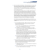
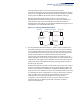
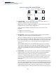
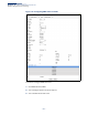
Table Of Contents
- How to Use This Guide
- Contents
- Figures
- Tables
- Getting Started
- Web Configuration
- Using the Web Interface
- Basic Management Tasks
- Displaying System Information
- Displaying Hardware/Software Versions
- Configuring Support for Jumbo Frames
- Displaying Bridge Extension Capabilities
- Managing System Files
- Setting the System Clock
- Configuring the Console Port
- Configuring Telnet Settings
- Displaying CPU Utilization
- Configuring CPU Guard
- Displaying Memory Utilization
- Resetting the System
- Interface Configuration
- VLAN Configuration
- Address Table Settings
- Spanning Tree Algorithm
- Congestion Control
- Class of Service
- Quality of Service
- VoIP Traffic Configuration
- Security Measures
- AAA (Authentication, Authorization and Accounting)
- Configuring User Accounts
- Web Authentication
- Network Access (MAC Address Authentication)
- Configuring HTTPS
- Configuring the Secure Shell
- Access Control Lists
- Filtering IP Addresses for Management Access
- Configuring Port Security
- Configuring 802.1X Port Authentication
- DoS Protection
- DHCP Snooping
- DHCPv6 Snooping
- ND Snooping
- IPv4 Source Guard
- IPv6 Source Guard
- ARP Inspection
- Application Filter
- Basic Administration Protocols
- Configuring Event Logging
- Link Layer Discovery Protocol
- Simple Network Management Protocol
- Configuring Global Settings for SNMP
- Setting Community Access Strings
- Setting the Local Engine ID
- Specifying a Remote Engine ID
- Setting SNMPv3 Views
- Configuring SNMPv3 Groups
- Configuring Local SNMPv3 Users
- Configuring Remote SNMPv3 Users
- Specifying Trap Managers
- Creating SNMP Notification Logs
- Showing SNMP Statistics
- Remote Monitoring
- Switch Clustering
- Setting a Time Range
- Ethernet Ring Protection Switching
- OAM Configuration
- UDLD Configuration
- LBD Configuration
- Multicast Filtering
- Overview
- Layer 2 IGMP (Snooping and Query for IPv4)
- Configuring IGMP Snooping and Query Parameters
- Specifying Static Interfaces for a Multicast Router
- Assigning Interfaces to Multicast Services
- Setting IGMP Snooping Status per Interface
- Filtering IGMP Packets on an Interface
- Displaying Multicast Groups Discovered by IGMP Snooping
- Displaying IGMP Snooping Statistics
- Filtering and Throttling IGMP Groups
- MLD Snooping (Snooping and Query for IPv6)
- Configuring MLD Snooping and Query Parameters
- Setting Immediate Leave Status for MLD Snooping per Interface
- Specifying Static Interfaces for an IPv6 Multicast Router
- Assigning Interfaces to IPv6 Multicast Services
- Filtering MLD Query Packets on an Interface
- Showing MLD Snooping Groups and Source List
- Displaying MLD Snooping Statistics
- Filtering and Throttling MLD Groups
- Multicast VLAN Registration for IPv4
- IP Tools
- IP Configuration
- General IP Routing
- IP Services
- Appendices

Chapter 13
| Basic Administration Protocols
Ethernet Ring Protection Switching
– 486 –
Figure 314: Sub-ring without Virtual Channel
◆ R-APS Def MAC – Sets the switch’s MAC address to be used as the node
identifier in R-APS messages. (Default: Enabled)
When ring nodes running ERPSv1 and ERPSv2 co-exist on the same ring, the
Ring ID of each ring node must be configured as “1”.
If this command is disabled, the following strings are used as the node
identifier:
■
ERPSv1: 01-19-A7-00-00-01
■
ERPSv2: 01-19-A7-00-00-[Ring ID]
◆ Propagate TC – Enables propagation of topology change messages from a
secondary ring to the primary ring. (Default: Disabled)
When a secondary ring detects a topology change, it can pass a message about
this event to the major ring. When the major ring receives this kind of message
from a secondary ring, it can clear the MAC addresses on its ring ports to help
the second ay ring restore its connections more quickly through protection
switching.
When the MAC addresses are cleared, data traffic may flood onto the major
ring. The data traffic will become stable after the MAC addresses are learned
again. The major ring will not be broken, but the bandwidth of data traffic on
the major ring may suffer for a short period of time due to this flooding
behavior.
◆ Holdoff Timer – The hold-off timer is used to filter out intermittent link faults.
Faults will only be reported to the ring protection mechanism if this timer
expires. (Range: 0-10000 milliseconds, in steps of 100 milliseconds)
In order to coordinate timing of protection switches at multiple layers, a hold-
off timer may be required. Its purpose is to allow, for example, a server layer
protection switch to have a chance to fix the problem before switching at a
client layer.
When a new defect or more severe defect occurs (new Signal Failure), this event
will not be reported immediately to the protection switching mechanism if the
provisioned hold-off timer value is non-zero. Instead, the hold-off timer will be
started. When the timer expires, whether a defect still exists or not, the timer
will be checked. If one does exist, that defect will be reported to the protection
Sub-ring
with Virtual
Channel
RPL Port
Interconnection Node
Ring Node
Major Ring