
Web Management Guide-R01
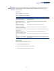
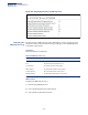

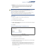
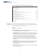
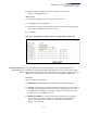
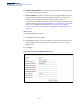
Table Of Contents
- How to Use This Guide
- Contents
- Figures
- Tables
- Getting Started
- Web Configuration
- Using the Web Interface
- Basic Management Tasks
- Displaying System Information
- Displaying Hardware/Software Versions
- Configuring Support for Jumbo Frames
- Displaying Bridge Extension Capabilities
- Managing System Files
- Setting the System Clock
- Configuring the Console Port
- Configuring Telnet Settings
- Displaying CPU Utilization
- Configuring CPU Guard
- Displaying Memory Utilization
- Resetting the System
- Interface Configuration
- VLAN Configuration
- Address Table Settings
- Spanning Tree Algorithm
- Congestion Control
- Class of Service
- Quality of Service
- VoIP Traffic Configuration
- Security Measures
- AAA (Authentication, Authorization and Accounting)
- Configuring User Accounts
- Web Authentication
- Network Access (MAC Address Authentication)
- Configuring HTTPS
- Configuring the Secure Shell
- Access Control Lists
- Filtering IP Addresses for Management Access
- Configuring Port Security
- Configuring 802.1X Port Authentication
- DoS Protection
- DHCP Snooping
- DHCPv6 Snooping
- ND Snooping
- IPv4 Source Guard
- IPv6 Source Guard
- ARP Inspection
- Application Filter
- Basic Administration Protocols
- Configuring Event Logging
- Link Layer Discovery Protocol
- Simple Network Management Protocol
- Configuring Global Settings for SNMP
- Setting Community Access Strings
- Setting the Local Engine ID
- Specifying a Remote Engine ID
- Setting SNMPv3 Views
- Configuring SNMPv3 Groups
- Configuring Local SNMPv3 Users
- Configuring Remote SNMPv3 Users
- Specifying Trap Managers
- Creating SNMP Notification Logs
- Showing SNMP Statistics
- Remote Monitoring
- Switch Clustering
- Setting a Time Range
- Ethernet Ring Protection Switching
- OAM Configuration
- UDLD Configuration
- LBD Configuration
- Multicast Filtering
- Overview
- Layer 2 IGMP (Snooping and Query for IPv4)
- Configuring IGMP Snooping and Query Parameters
- Specifying Static Interfaces for a Multicast Router
- Assigning Interfaces to Multicast Services
- Setting IGMP Snooping Status per Interface
- Filtering IGMP Packets on an Interface
- Displaying Multicast Groups Discovered by IGMP Snooping
- Displaying IGMP Snooping Statistics
- Filtering and Throttling IGMP Groups
- MLD Snooping (Snooping and Query for IPv6)
- Configuring MLD Snooping and Query Parameters
- Setting Immediate Leave Status for MLD Snooping per Interface
- Specifying Static Interfaces for an IPv6 Multicast Router
- Assigning Interfaces to IPv6 Multicast Services
- Filtering MLD Query Packets on an Interface
- Showing MLD Snooping Groups and Source List
- Displaying MLD Snooping Statistics
- Filtering and Throttling MLD Groups
- Multicast VLAN Registration for IPv4
- IP Tools
- IP Configuration
- General IP Routing
- IP Services
- Appendices

Chapter 13
| Basic Administration Protocols
Configuring Event Logging
– 396 –
Configuring Event Logging
The switch allows you to control the logging of error messages, including the type
of events that are recorded in switch memory, logging to a remote System Log
(syslog) server, and displays a list of recent event messages.
System Log
Configuration
Use the Administration > Log > System (Configure Global) page to enable or
disable event logging, and specify which levels are logged to RAM or flash memory.
Severe error messages that are logged to flash memory are permanently stored in
the switch to assist in troubleshooting network problems. Up to 4096 log entries
can be stored in the flash memory, with the oldest entries being overwritten first
when the available log memory (256 kilobytes) has been exceeded.
The System Logs page allows you to configure and limit system messages that are
logged to flash or RAM memory. The default is for event levels 0 to 3 to be logged
to flash and levels 0 to 7 to be logged to RAM.
Parameters
These parameters are displayed:
◆ System Log Status – Enables/disables the logging of debug or error messages
to the logging process. (Default: Enabled)
◆ Flash Level – Limits log messages saved to the switch’s permanent flash
memory for all levels up to the specified level. For example, if level 3 is
specified, all messages from level 0 to level 3 will be logged to flash.
(Range: 0-7, Default: 3)
Table 25: Logging Levels
Level Severity Name Description
7
*
* There are only Level 2, 5 and 6 error messages for the current firmware release.
Debugging Debugging messages
6 Informational Informational messages only
5 Notice Normal but significant condition, such as cold start
4 Warning Warning conditions (e.g., return false, unexpected
return)
3 Error Error conditions (e.g., invalid input, default used)
2 Critical Critical conditions (e.g., memory allocation, or free
memory error - resource exhausted)
1 Alert Immediate action needed
0 Emergency System unusable