
Web Management Guide-R01
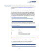
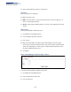
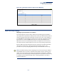
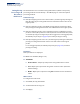
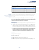
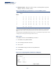
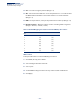
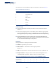
Table Of Contents
- How to Use This Guide
- Contents
- Figures
- Tables
- Getting Started
- Web Configuration
- Using the Web Interface
- Basic Management Tasks
- Displaying System Information
- Displaying Hardware/Software Versions
- Configuring Support for Jumbo Frames
- Displaying Bridge Extension Capabilities
- Managing System Files
- Setting the System Clock
- Configuring the Console Port
- Configuring Telnet Settings
- Displaying CPU Utilization
- Configuring CPU Guard
- Displaying Memory Utilization
- Resetting the System
- Interface Configuration
- VLAN Configuration
- Address Table Settings
- Spanning Tree Algorithm
- Congestion Control
- Class of Service
- Quality of Service
- VoIP Traffic Configuration
- Security Measures
- AAA (Authentication, Authorization and Accounting)
- Configuring User Accounts
- Web Authentication
- Network Access (MAC Address Authentication)
- Configuring HTTPS
- Configuring the Secure Shell
- Access Control Lists
- Filtering IP Addresses for Management Access
- Configuring Port Security
- Configuring 802.1X Port Authentication
- DoS Protection
- DHCP Snooping
- DHCPv6 Snooping
- ND Snooping
- IPv4 Source Guard
- IPv6 Source Guard
- ARP Inspection
- Application Filter
- Basic Administration Protocols
- Configuring Event Logging
- Link Layer Discovery Protocol
- Simple Network Management Protocol
- Configuring Global Settings for SNMP
- Setting Community Access Strings
- Setting the Local Engine ID
- Specifying a Remote Engine ID
- Setting SNMPv3 Views
- Configuring SNMPv3 Groups
- Configuring Local SNMPv3 Users
- Configuring Remote SNMPv3 Users
- Specifying Trap Managers
- Creating SNMP Notification Logs
- Showing SNMP Statistics
- Remote Monitoring
- Switch Clustering
- Setting a Time Range
- Ethernet Ring Protection Switching
- OAM Configuration
- UDLD Configuration
- LBD Configuration
- Multicast Filtering
- Overview
- Layer 2 IGMP (Snooping and Query for IPv4)
- Configuring IGMP Snooping and Query Parameters
- Specifying Static Interfaces for a Multicast Router
- Assigning Interfaces to Multicast Services
- Setting IGMP Snooping Status per Interface
- Filtering IGMP Packets on an Interface
- Displaying Multicast Groups Discovered by IGMP Snooping
- Displaying IGMP Snooping Statistics
- Filtering and Throttling IGMP Groups
- MLD Snooping (Snooping and Query for IPv6)
- Configuring MLD Snooping and Query Parameters
- Setting Immediate Leave Status for MLD Snooping per Interface
- Specifying Static Interfaces for an IPv6 Multicast Router
- Assigning Interfaces to IPv6 Multicast Services
- Filtering MLD Query Packets on an Interface
- Showing MLD Snooping Groups and Source List
- Displaying MLD Snooping Statistics
- Filtering and Throttling MLD Groups
- Multicast VLAN Registration for IPv4
- IP Tools
- IP Configuration
- General IP Routing
- IP Services
- Appendices

Chapter 9
| Class of Service
Layer 2 Queue Settings
– 241 –
Mapping CoS Values
to Egress Queues
Use the Traffic > Priority > PHB to Queue page to specify the hardware output
queues to use based on the internal per-hop behavior value. (For more information
on exact manner in which the ingress priority tags are mapped to egress queues for
internal processing, see “Mapping CoS Priorities to Internal DSCP Values” on
page 247).
The switch processes Class of Service (CoS) priority tagged traffic by using eight
priority queues for each port, with service schedules based on strict priority,
Weighted Round-Robin (WRR), or a combination of strict and weighted queuing.
Up to eight separate traffic priorities are defined in IEEE 802.1p. Default priority
levels are assigned according to recommendations in the IEEE 802.1p standard as
shown in Table 13. The following table indicates the default mapping of internal
per-hop behavior to the hardware queues. The actual mapping may differ if the
CoS priorities to internal DSCP values have been modified.
The priority levels recommended in the IEEE 802.1p standard for various network
applications are shown in Table 14. However, priority levels can be mapped to the
switch’s output queues in any way that benefits application traffic for the network.
Command Usage
◆ Egress packets are placed into the hardware queues according to the mapping
defined by this command.
◆ The default internal PHB to output queue mapping is shown below.
Table 13: IEEE 802.1p Egress Queue Priority Mapping
Priority 01234567
Queue 20134567
Table 14: CoS Priority Levels
Priority Level Traffic Type
1 Background
2(Spare)
0 (default) Best Effort
3Excellent Effort
4 Controlled Load
5 Video, less than 100 milliseconds latency and jitter
6 Voice, less than 10 milliseconds latency and jitter
7Network Control
Table 15: Mapping Internal Per-hop Behavior to Hardware Queues
Per-hop Behavior 0 1 2 3 4 5 6 7
Hardware Queues 2 0 1 3 4 5 6 7