
Web Management Guide-R04
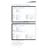
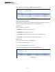
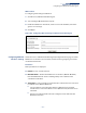
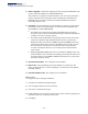
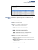
Table Of Contents
- How to Use This Guide
- Contents
- Figures
- Tables
- Getting Started
- Web Configuration
- Using the Web Interface
- Basic Management Tasks
- Displaying System Information
- Displaying Hardware/Software Versions
- Configuring Support for Jumbo Frames
- Displaying Bridge Extension Capabilities
- Managing System Files
- Setting the System Clock
- Configuring the Console Port
- Configuring Telnet Settings
- Displaying CPU Utilization
- Configuring CPU Guard
- Displaying Memory Utilization
- Resetting the System
- Interface Configuration
- VLAN Configuration
- Address Table Settings
- Spanning Tree Algorithm
- Congestion Control
- Class of Service
- Layer 2 Queue Settings
- Layer 3/4 Priority Settings
- Setting Priority Processing to IP Precedence/DSCP or CoS
- Mapping Ingress DSCP Values to Internal DSCP Values
- Mapping CoS Priorities to Internal DSCP Values
- Mapping Internal DSCP Values to Egress CoS Values
- Mapping IP Precedence Values to Internal DSCP Values
- Mapping IP Port Priority to Internal DSCP Values
- Quality of Service
- VoIP Traffic Configuration
- Security Measures
- AAA Authentication, Authorization and Accounting
- Configuring User Accounts
- Web Authentication
- Network Access (MAC Address Authentication)
- Configuring HTTPS
- Configuring the Secure Shell
- Access Control Lists
- Filtering IP Addresses for Management Access
- Configuring Port Security
- Configuring 802.1X Port Authentication
- DoS Protection
- DHCPv4 Snooping
- DHCPv6 Snooping
- IPv4 Source Guard
- IPv6 Source Guard
- ARP Inspection
- Application Filter
- Basic Administration Protocols
- Configuring Event Logging
- Link Layer Discovery Protocol
- Simple Network Management Protocol
- Configuring Global Settings for SNMP
- Setting Community Access Strings
- Setting the Local Engine ID
- Specifying a Remote Engine ID
- Setting SNMPv3 Views
- Configuring SNMPv3 Groups
- Configuring Local SNMPv3 Users
- Configuring Remote SNMPv3 Users
- Specifying Trap Managers
- Creating SNMP Notification Logs
- Showing SNMP Statistics
- Remote Monitoring
- Switch Clustering
- Setting a Time Range
- Ethernet Ring Protection Switching
- OAM Configuration
- Connectivity Fault Management
- Configuring Global Settings for CFM
- Configuring Interfaces for CFM
- Configuring CFM Maintenance Domains
- Configuring CFM Maintenance Associations
- Configuring Maintenance End Points
- Configuring Remote Maintenance End Points
- Transmitting Link Trace Messages
- Transmitting Loop Back Messages
- Transmitting Delay-Measure Requests
- Displaying Local MEPs
- Displaying Details for Local MEPs
- Displaying Local MIPs
- Displaying Remote MEPs
- Displaying Details for Remote MEPs
- Displaying the Link Trace Cache
- Displaying Fault Notification Settings
- Displaying Continuity Check Errors
- OAM Configuration
- UDLD Configuration
- LBD Configuration
- Smart Pair Configuration
- Multicast Filtering
- Overview
- Layer 2 IGMP (Snooping and Query for IPv4)
- Configuring IGMP Snooping and Query Parameters
- Specifying Static Interfaces for a Multicast Router
- Assigning Interfaces to Multicast Services
- Setting IGMP Snooping Status per Interface
- Filtering IGMP Query Packets and Multicast Data
- Displaying Multicast Groups Discovered by IGMP Snooping
- Displaying IGMP Snooping Statistics
- Filtering and Throttling IGMP Groups
- MLD Snooping (Snooping and Query for IPv6)
- Multicast VLAN Registration for IPv4
- Multicast VLAN Registration for IPv6
- Basic IP Functions
- IP Configuration
- General IP Routing
- IP Services
- Appendices
- Glossary

Chapter 18
| IP Services
Dynamic Host Configuration Protocol
– 711 –
found, it assigns an address from the matching network address pool. However,
if no matching address pool is found the request is ignored.
◆ When searching for a manual binding, the switch compares the client identifier
and then the hardware address for DHCP clients. Since BOOTP clients cannot
transmit a client identifier, you must configure a hardware address for this host
type. If no manual binding has been specified for a host entry with a hardware
address or client identifier, the switch will assign an address from the first
matching network pool.
◆ If the subnet mask is not specified for network or host address pools, the class
A, B, or C natural mask is used (see “Specifying Network Interfaces” on
page 703). The DHCP server assumes that all host addresses are available. You
can exclude subsets of the address space by using the IP Service > DHCP >
Server (Configure Excluded Addresses – Add) page.
Parameters
These parameters are displayed:
Creating a New Address Pool
◆ Pool Name – A string or integer. (Range: 1-32 characters)
◆ Type – Sets the address pool type to Network or Host.
Setting Parameters for a Network Pool
◆ IP – The IP address of the DHCP address pool.
◆ Subnet Mask – The bit combination that identifies the network (or subnet) and
the host portion of the DHCP address pool.
Setting Parameters for a Static Host
◆ IP – The IP address to assign to the host.
◆ Subnet Mask – Specifies the network mask of the client.
◆ Client-Identifier – A unique designation for the client device, either a text
string (1-15 characters) or hexadecimal value. The information included in the
identifier is based on RFC 2132 Option 60, and must be unique for all clients in
the same administrative domain.
◆ Hardware Address – Specifies the MAC address and protocol used on the
client. (Options: Ethernet, IEEE802, FDDI, None; Default: Ethernet)
Setting Optional Parameters
◆ Default Router – The IP address of the primary and alternate gateway router.
The IP address of the router should be on the same subnet as the client.