
Web Management Guide-R04

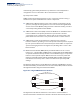
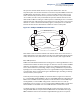
Table Of Contents
- How to Use This Guide
- Contents
- Figures
- Tables
- Getting Started
- Web Configuration
- Using the Web Interface
- Basic Management Tasks
- Displaying System Information
- Displaying Hardware/Software Versions
- Configuring Support for Jumbo Frames
- Displaying Bridge Extension Capabilities
- Managing System Files
- Setting the System Clock
- Configuring the Console Port
- Configuring Telnet Settings
- Displaying CPU Utilization
- Configuring CPU Guard
- Displaying Memory Utilization
- Resetting the System
- Interface Configuration
- VLAN Configuration
- Address Table Settings
- Spanning Tree Algorithm
- Congestion Control
- Class of Service
- Layer 2 Queue Settings
- Layer 3/4 Priority Settings
- Setting Priority Processing to IP Precedence/DSCP or CoS
- Mapping Ingress DSCP Values to Internal DSCP Values
- Mapping CoS Priorities to Internal DSCP Values
- Mapping Internal DSCP Values to Egress CoS Values
- Mapping IP Precedence Values to Internal DSCP Values
- Mapping IP Port Priority to Internal DSCP Values
- Quality of Service
- VoIP Traffic Configuration
- Security Measures
- AAA Authentication, Authorization and Accounting
- Configuring User Accounts
- Web Authentication
- Network Access (MAC Address Authentication)
- Configuring HTTPS
- Configuring the Secure Shell
- Access Control Lists
- Filtering IP Addresses for Management Access
- Configuring Port Security
- Configuring 802.1X Port Authentication
- DoS Protection
- DHCPv4 Snooping
- DHCPv6 Snooping
- IPv4 Source Guard
- IPv6 Source Guard
- ARP Inspection
- Application Filter
- Basic Administration Protocols
- Configuring Event Logging
- Link Layer Discovery Protocol
- Simple Network Management Protocol
- Configuring Global Settings for SNMP
- Setting Community Access Strings
- Setting the Local Engine ID
- Specifying a Remote Engine ID
- Setting SNMPv3 Views
- Configuring SNMPv3 Groups
- Configuring Local SNMPv3 Users
- Configuring Remote SNMPv3 Users
- Specifying Trap Managers
- Creating SNMP Notification Logs
- Showing SNMP Statistics
- Remote Monitoring
- Switch Clustering
- Setting a Time Range
- Ethernet Ring Protection Switching
- OAM Configuration
- Connectivity Fault Management
- Configuring Global Settings for CFM
- Configuring Interfaces for CFM
- Configuring CFM Maintenance Domains
- Configuring CFM Maintenance Associations
- Configuring Maintenance End Points
- Configuring Remote Maintenance End Points
- Transmitting Link Trace Messages
- Transmitting Loop Back Messages
- Transmitting Delay-Measure Requests
- Displaying Local MEPs
- Displaying Details for Local MEPs
- Displaying Local MIPs
- Displaying Remote MEPs
- Displaying Details for Remote MEPs
- Displaying the Link Trace Cache
- Displaying Fault Notification Settings
- Displaying Continuity Check Errors
- OAM Configuration
- UDLD Configuration
- LBD Configuration
- Smart Pair Configuration
- Multicast Filtering
- Overview
- Layer 2 IGMP (Snooping and Query for IPv4)
- Configuring IGMP Snooping and Query Parameters
- Specifying Static Interfaces for a Multicast Router
- Assigning Interfaces to Multicast Services
- Setting IGMP Snooping Status per Interface
- Filtering IGMP Query Packets and Multicast Data
- Displaying Multicast Groups Discovered by IGMP Snooping
- Displaying IGMP Snooping Statistics
- Filtering and Throttling IGMP Groups
- MLD Snooping (Snooping and Query for IPv6)
- Multicast VLAN Registration for IPv4
- Multicast VLAN Registration for IPv6
- Basic IP Functions
- IP Configuration
- General IP Routing
- IP Services
- Appendices
- Glossary

Chapter 13
| Basic Administration Protocols
Connectivity Fault Management
– 520 –
message can also be sent using the MEP’s identifier. A reply indicates that the
destination is reachable.
Link trace messages are used for fault verification. These messages are multicast
frames sent out to track the hop-by-hop path to a target MEP within the same MA.
Responses provide information on the ingress, egress, and relay action taken at
each hop along the path, providing vital information about connectivity problems.
Responses allow the sender to discover all of the maintenance points that would be
traversed by a data frame sent to the target MAC address.
SNMP traps can also be configured to provide an automated method of fault
notification. If the fault notification generator detects one or more defects within
the configured time period, and fault alarms are enabled, a corresponding trap will
be sent. No further fault alarms are sent until the fault notification generator has
been reset by the passage of a configured time period without detecting any
further faults. Upon receiving a fault alarm, you should inspect the related SNMP
objects for the reporting MEP, diagnose the fault, correct it, and re-examine the
MEP’s SNMP objects to see whether the fault notification generator has been reset.
Configuration Guidelines
1. Configure the maintenance domains with the MD List (see "Configuring CFM
Maintenance Domains").
2. Configure the maintenance associations with MA List (see "Configuring CFM
Maintenance Associations").
3. Configure the local maintenance end points (MEPs) which will serve as the
domain service access points for the specified maintenance association using
the MEP List (see "Configuring CFM Maintenance Associations").
4. Enter a static list of MEPs assigned to other devices within the same
maintenance association using the Remote MEP List (see "Configuring
Remote Maintenance End Points"). This allows CFM to automatically verify the
functionality of these remote end points by cross-checking the static list
configured on this device against information learned through continuity
check messages.
5. Enable CFM globally on the switch using the Configure Global screen (see
"Configuring Global Settings for CFM").
6. Enable CFM on the local MEPs using the Configure Interface screen (see
"Configuring Interfaces for CFM").
7. Enable continuity check and cross-check operations, and configure AIS
parameters using the Configure MA – Configure Details screen (see
"Configuring CFM Maintenance Associations").
Other configuration changes may be required for your particular environment,
such as adjusting the interval at which continuity check messages are sent (see