
Web Management Guide-R04

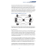
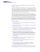
Table Of Contents
- How to Use This Guide
- Contents
- Figures
- Tables
- Getting Started
- Web Configuration
- Using the Web Interface
- Basic Management Tasks
- Displaying System Information
- Displaying Hardware/Software Versions
- Configuring Support for Jumbo Frames
- Displaying Bridge Extension Capabilities
- Managing System Files
- Setting the System Clock
- Configuring the Console Port
- Configuring Telnet Settings
- Displaying CPU Utilization
- Configuring CPU Guard
- Displaying Memory Utilization
- Resetting the System
- Interface Configuration
- VLAN Configuration
- Address Table Settings
- Spanning Tree Algorithm
- Congestion Control
- Class of Service
- Layer 2 Queue Settings
- Layer 3/4 Priority Settings
- Setting Priority Processing to IP Precedence/DSCP or CoS
- Mapping Ingress DSCP Values to Internal DSCP Values
- Mapping CoS Priorities to Internal DSCP Values
- Mapping Internal DSCP Values to Egress CoS Values
- Mapping IP Precedence Values to Internal DSCP Values
- Mapping IP Port Priority to Internal DSCP Values
- Quality of Service
- VoIP Traffic Configuration
- Security Measures
- AAA Authentication, Authorization and Accounting
- Configuring User Accounts
- Web Authentication
- Network Access (MAC Address Authentication)
- Configuring HTTPS
- Configuring the Secure Shell
- Access Control Lists
- Filtering IP Addresses for Management Access
- Configuring Port Security
- Configuring 802.1X Port Authentication
- DoS Protection
- DHCPv4 Snooping
- DHCPv6 Snooping
- IPv4 Source Guard
- IPv6 Source Guard
- ARP Inspection
- Application Filter
- Basic Administration Protocols
- Configuring Event Logging
- Link Layer Discovery Protocol
- Simple Network Management Protocol
- Configuring Global Settings for SNMP
- Setting Community Access Strings
- Setting the Local Engine ID
- Specifying a Remote Engine ID
- Setting SNMPv3 Views
- Configuring SNMPv3 Groups
- Configuring Local SNMPv3 Users
- Configuring Remote SNMPv3 Users
- Specifying Trap Managers
- Creating SNMP Notification Logs
- Showing SNMP Statistics
- Remote Monitoring
- Switch Clustering
- Setting a Time Range
- Ethernet Ring Protection Switching
- OAM Configuration
- Connectivity Fault Management
- Configuring Global Settings for CFM
- Configuring Interfaces for CFM
- Configuring CFM Maintenance Domains
- Configuring CFM Maintenance Associations
- Configuring Maintenance End Points
- Configuring Remote Maintenance End Points
- Transmitting Link Trace Messages
- Transmitting Loop Back Messages
- Transmitting Delay-Measure Requests
- Displaying Local MEPs
- Displaying Details for Local MEPs
- Displaying Local MIPs
- Displaying Remote MEPs
- Displaying Details for Remote MEPs
- Displaying the Link Trace Cache
- Displaying Fault Notification Settings
- Displaying Continuity Check Errors
- OAM Configuration
- UDLD Configuration
- LBD Configuration
- Smart Pair Configuration
- Multicast Filtering
- Overview
- Layer 2 IGMP (Snooping and Query for IPv4)
- Configuring IGMP Snooping and Query Parameters
- Specifying Static Interfaces for a Multicast Router
- Assigning Interfaces to Multicast Services
- Setting IGMP Snooping Status per Interface
- Filtering IGMP Query Packets and Multicast Data
- Displaying Multicast Groups Discovered by IGMP Snooping
- Displaying IGMP Snooping Statistics
- Filtering and Throttling IGMP Groups
- MLD Snooping (Snooping and Query for IPv6)
- Multicast VLAN Registration for IPv4
- Multicast VLAN Registration for IPv6
- Basic IP Functions
- IP Configuration
- General IP Routing
- IP Services
- Appendices
- Glossary

Chapter 13
| Basic Administration Protocols
Connectivity Fault Management
– 519 –
two operator domains which include access points marked “O
1
” and “O
2
”
respectively. The users of these domains can see their respective MEPs as well as all
the MIPs within their domains. There is a service provider domain at the second
level in the hierarchy. From the service provider’s view, the access points marked
“P” are visible, and all access points within the operator domains have also been
made visible as MIPs according to common practice. And finally, there is a customer
domain at the top of the hierarchy. Users at this level can only see the access points
marked “C” on the outer domain boundary. Again, normal practice is to hide the
internal structure of the network from outsiders to reduce security risks.
Figure 337: Multiple CFM Maintenance Domains
Note that the Service Instances within each domain shown above are based on a
unique maintenance association for the specific users, distinguished by the domain
name, maintenance level, maintenance association’s name, and assigned VLAN.
Basic CFM Operations
CFM uses standard Ethernet frames for sending protocol messages. Both the source
and destination address for these messages are based on unicast or multicast MAC
addresses, and therefore confined to a single Layer 2 CFM service VLAN. For this
reason, the transmission, forwarding, and processing of CFM frames is performed
by bridges, not routers. Bridges that do not recognize CFM messages forward them
as normal data. There are three basic types of CFM messages, including continuity
check, link trace, and loop back.
Continuity check messages (CCMs) are multicast within a single Service Instance
(i.e., a specific MA), allowing MEPs to discover other MEPs within the same MA, and
MIPs to discover MEPs. Connectivity faults are indicated when a known MEP stops
sending CCMs, or a remote MEP configured in a static list does not come up.
Configuration errors, such as a cross-connect between different MAs, are indicated
when a CCM is received with an incorrect MA identifier or maintenance level.
Loopback messages are used for fault verification. These messages can be sent
using the MAC address of any destination MEP within the same MA. If the target
MEP’s identifier has been discovered through CCM messages, then a loop back
Customer MA
Provider MA
Operator 1 MA Operator 2 MA
C
C
C
C
O
1
O
1
P
O
2
O
2
P
P
O
1
O
2
P