
Web Management Guide-R04
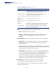
Table Of Contents
- How to Use This Guide
- Contents
- Figures
- Tables
- Getting Started
- Web Configuration
- Using the Web Interface
- Basic Management Tasks
- Displaying System Information
- Displaying Hardware/Software Versions
- Configuring Support for Jumbo Frames
- Displaying Bridge Extension Capabilities
- Managing System Files
- Setting the System Clock
- Configuring the Console Port
- Configuring Telnet Settings
- Displaying CPU Utilization
- Configuring CPU Guard
- Displaying Memory Utilization
- Resetting the System
- Interface Configuration
- VLAN Configuration
- Address Table Settings
- Spanning Tree Algorithm
- Congestion Control
- Class of Service
- Layer 2 Queue Settings
- Layer 3/4 Priority Settings
- Setting Priority Processing to IP Precedence/DSCP or CoS
- Mapping Ingress DSCP Values to Internal DSCP Values
- Mapping CoS Priorities to Internal DSCP Values
- Mapping Internal DSCP Values to Egress CoS Values
- Mapping IP Precedence Values to Internal DSCP Values
- Mapping IP Port Priority to Internal DSCP Values
- Quality of Service
- VoIP Traffic Configuration
- Security Measures
- AAA Authentication, Authorization and Accounting
- Configuring User Accounts
- Web Authentication
- Network Access (MAC Address Authentication)
- Configuring HTTPS
- Configuring the Secure Shell
- Access Control Lists
- Filtering IP Addresses for Management Access
- Configuring Port Security
- Configuring 802.1X Port Authentication
- DoS Protection
- DHCPv4 Snooping
- DHCPv6 Snooping
- IPv4 Source Guard
- IPv6 Source Guard
- ARP Inspection
- Application Filter
- Basic Administration Protocols
- Configuring Event Logging
- Link Layer Discovery Protocol
- Simple Network Management Protocol
- Configuring Global Settings for SNMP
- Setting Community Access Strings
- Setting the Local Engine ID
- Specifying a Remote Engine ID
- Setting SNMPv3 Views
- Configuring SNMPv3 Groups
- Configuring Local SNMPv3 Users
- Configuring Remote SNMPv3 Users
- Specifying Trap Managers
- Creating SNMP Notification Logs
- Showing SNMP Statistics
- Remote Monitoring
- Switch Clustering
- Setting a Time Range
- Ethernet Ring Protection Switching
- OAM Configuration
- Connectivity Fault Management
- Configuring Global Settings for CFM
- Configuring Interfaces for CFM
- Configuring CFM Maintenance Domains
- Configuring CFM Maintenance Associations
- Configuring Maintenance End Points
- Configuring Remote Maintenance End Points
- Transmitting Link Trace Messages
- Transmitting Loop Back Messages
- Transmitting Delay-Measure Requests
- Displaying Local MEPs
- Displaying Details for Local MEPs
- Displaying Local MIPs
- Displaying Remote MEPs
- Displaying Details for Remote MEPs
- Displaying the Link Trace Cache
- Displaying Fault Notification Settings
- Displaying Continuity Check Errors
- OAM Configuration
- UDLD Configuration
- LBD Configuration
- Smart Pair Configuration
- Multicast Filtering
- Overview
- Layer 2 IGMP (Snooping and Query for IPv4)
- Configuring IGMP Snooping and Query Parameters
- Specifying Static Interfaces for a Multicast Router
- Assigning Interfaces to Multicast Services
- Setting IGMP Snooping Status per Interface
- Filtering IGMP Query Packets and Multicast Data
- Displaying Multicast Groups Discovered by IGMP Snooping
- Displaying IGMP Snooping Statistics
- Filtering and Throttling IGMP Groups
- MLD Snooping (Snooping and Query for IPv6)
- Multicast VLAN Registration for IPv4
- Multicast VLAN Registration for IPv6
- Basic IP Functions
- IP Configuration
- General IP Routing
- IP Services
- Appendices
- Glossary

Chapter 13
| Basic Administration Protocols
OAM Configuration
– 510 –
◆ Mode – Sets the OAM operation mode. (Default: Active)
■
Active – All OAM functions are enabled.
■
Passive – All OAM functions are enabled, except for OAM discovery,
sending variable request OAMPDUs, and sending loopback control
OAMPDUs.
◆ Critical Link Event – Controls reporting of critical link events to its OAM peer.
■
Dying Gasp - If an unrecoverable condition occurs, the local OAM entity
(i.e., this switch) indicates this by immediately sending trap message.
(Default: Enabled)
Dying gasp events are caused by an unrecoverable failure, such as a power
failure or device reset. When system power fails, the switch will always send
a dying gasp trap message prior to power down.
■
Critical Event – If a critical event occurs, the local OAM entity indicates this
to its peer by setting the appropriate flag in the next OAMPDU to be sent
and stores this information in its OAM event log. (Default: Enabled)
Critical events include various failures, such as abnormal voltage
fluctuations, out-of-range temperature detected, fan failure, CRC error in
flash memory, insufficient memory, or other hardware faults.
◆ Errored Frame – Controls reporting of errored frame link events.
An errored frame is a frame in which one or more bits are errored.
An errored frame link event occurs if the threshold is reached or exceeded
within the specified period.
Active Send Local This value is used by active mode devices and indicates the OAM
entity is actively trying to discover whether the peer has OAM
capability but has not yet made that determination.
Send Local And Remote The local OAM entity has discovered the peer but has not yet
accepted or rejected the configuration of the peer.
Send Local And Remote
OK
OAM peering is allowed by the local device.
OAM Peering Locally
Rejected
The local OAM entity rejects the peering.
OAM Peering Remotely
Rejected
The remote OAM entity rejects the peering.
Operational When the local OAM entity learns that both it and the remote OAM
entity have accepted the peering, the state moves to this state.
Non Oper Half Duplex This state is returned whenever Ethernet OAM is enabled but the
interface is in half-duplex operation.
Table 35: OAM Operation State (Continued)
State Description