
Web Management Guide-R04
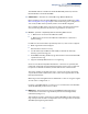
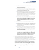
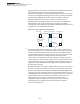
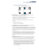
Table Of Contents
- How to Use This Guide
- Contents
- Figures
- Tables
- Getting Started
- Web Configuration
- Using the Web Interface
- Basic Management Tasks
- Displaying System Information
- Displaying Hardware/Software Versions
- Configuring Support for Jumbo Frames
- Displaying Bridge Extension Capabilities
- Managing System Files
- Setting the System Clock
- Configuring the Console Port
- Configuring Telnet Settings
- Displaying CPU Utilization
- Configuring CPU Guard
- Displaying Memory Utilization
- Resetting the System
- Interface Configuration
- VLAN Configuration
- Address Table Settings
- Spanning Tree Algorithm
- Congestion Control
- Class of Service
- Layer 2 Queue Settings
- Layer 3/4 Priority Settings
- Setting Priority Processing to IP Precedence/DSCP or CoS
- Mapping Ingress DSCP Values to Internal DSCP Values
- Mapping CoS Priorities to Internal DSCP Values
- Mapping Internal DSCP Values to Egress CoS Values
- Mapping IP Precedence Values to Internal DSCP Values
- Mapping IP Port Priority to Internal DSCP Values
- Quality of Service
- VoIP Traffic Configuration
- Security Measures
- AAA Authentication, Authorization and Accounting
- Configuring User Accounts
- Web Authentication
- Network Access (MAC Address Authentication)
- Configuring HTTPS
- Configuring the Secure Shell
- Access Control Lists
- Filtering IP Addresses for Management Access
- Configuring Port Security
- Configuring 802.1X Port Authentication
- DoS Protection
- DHCPv4 Snooping
- DHCPv6 Snooping
- IPv4 Source Guard
- IPv6 Source Guard
- ARP Inspection
- Application Filter
- Basic Administration Protocols
- Configuring Event Logging
- Link Layer Discovery Protocol
- Simple Network Management Protocol
- Configuring Global Settings for SNMP
- Setting Community Access Strings
- Setting the Local Engine ID
- Specifying a Remote Engine ID
- Setting SNMPv3 Views
- Configuring SNMPv3 Groups
- Configuring Local SNMPv3 Users
- Configuring Remote SNMPv3 Users
- Specifying Trap Managers
- Creating SNMP Notification Logs
- Showing SNMP Statistics
- Remote Monitoring
- Switch Clustering
- Setting a Time Range
- Ethernet Ring Protection Switching
- OAM Configuration
- Connectivity Fault Management
- Configuring Global Settings for CFM
- Configuring Interfaces for CFM
- Configuring CFM Maintenance Domains
- Configuring CFM Maintenance Associations
- Configuring Maintenance End Points
- Configuring Remote Maintenance End Points
- Transmitting Link Trace Messages
- Transmitting Loop Back Messages
- Transmitting Delay-Measure Requests
- Displaying Local MEPs
- Displaying Details for Local MEPs
- Displaying Local MIPs
- Displaying Remote MEPs
- Displaying Details for Remote MEPs
- Displaying the Link Trace Cache
- Displaying Fault Notification Settings
- Displaying Continuity Check Errors
- OAM Configuration
- UDLD Configuration
- LBD Configuration
- Smart Pair Configuration
- Multicast Filtering
- Overview
- Layer 2 IGMP (Snooping and Query for IPv4)
- Configuring IGMP Snooping and Query Parameters
- Specifying Static Interfaces for a Multicast Router
- Assigning Interfaces to Multicast Services
- Setting IGMP Snooping Status per Interface
- Filtering IGMP Query Packets and Multicast Data
- Displaying Multicast Groups Discovered by IGMP Snooping
- Displaying IGMP Snooping Statistics
- Filtering and Throttling IGMP Groups
- MLD Snooping (Snooping and Query for IPv6)
- Multicast VLAN Registration for IPv4
- Multicast VLAN Registration for IPv6
- Basic IP Functions
- IP Configuration
- General IP Routing
- IP Services
- Appendices
- Glossary

Chapter 13
| Basic Administration Protocols
Ethernet Ring Protection Switching
– 499 –
Figure 324: Sub-ring without Virtual Channel
◆ R-APS Def MAC – Sets the switch’s MAC address to be used as the node
identifier in R-APS messages. (Default: Enabled)
When ring nodes running ERPSv1 and ERPSv2 co-exist on the same ring, the
Ring ID of each ring node must be configured as “1”.
If this command is disabled, the following strings are used as the node
identifier:
■
ERPSv1: 01-19-A7-00-00-01
■
ERPSv2: 01-19-A7-00-00-[Ring ID]
◆ Propagate TC – Enables propagation of topology change messages from a
secondary ring to the primary ring. (Default: Disabled)
When a secondary ring detects a topology change, it can pass a message about
this event to the major ring. When the major ring receives this kind of message
from a secondary ring, it can clear the MAC addresses on its ring ports to help
the second ay ring restore its connections more quickly through protection
switching.
When the MAC addresses are cleared, data traffic may flood onto the major
ring. The data traffic will become stable after the MAC addresses are learned
again. The major ring will not be broken, but the bandwidth of data traffic on
the major ring may suffer for a short period of time due to this flooding
behavior.
◆ Non-ERPS Device Protection – Sends non-standard health-check packets
when an owner node enters protection state without any link down event
having been detected through Signal Fault messages. (Default: Disabled)
■
The RPL owner node detects a failed link when it receives R-APS (SF - signal
fault) messages from nodes adjacent to the failed link. The owner then
enters protection state by unblocking the RPL. However, using this
standard recovery procedure may cause a non-EPRS device to become
isolated when the ERPS device adjacent to it detects a continuity check
message (CCM) loss event and blocks the link between the non-ERPS
device and ERPS device.
Sub-ring
with Virtual
Channel
RPL Port
Interconnection Node
Ring Node
Major Ring