
Web Management Guide-R04
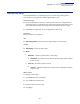
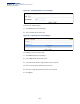
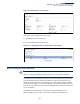
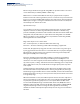
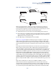
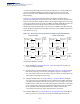
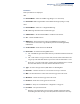
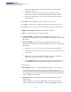
Table Of Contents
- How to Use This Guide
- Contents
- Figures
- Tables
- Getting Started
- Web Configuration
- Using the Web Interface
- Basic Management Tasks
- Displaying System Information
- Displaying Hardware/Software Versions
- Configuring Support for Jumbo Frames
- Displaying Bridge Extension Capabilities
- Managing System Files
- Setting the System Clock
- Configuring the Console Port
- Configuring Telnet Settings
- Displaying CPU Utilization
- Configuring CPU Guard
- Displaying Memory Utilization
- Resetting the System
- Interface Configuration
- VLAN Configuration
- Address Table Settings
- Spanning Tree Algorithm
- Congestion Control
- Class of Service
- Layer 2 Queue Settings
- Layer 3/4 Priority Settings
- Setting Priority Processing to IP Precedence/DSCP or CoS
- Mapping Ingress DSCP Values to Internal DSCP Values
- Mapping CoS Priorities to Internal DSCP Values
- Mapping Internal DSCP Values to Egress CoS Values
- Mapping IP Precedence Values to Internal DSCP Values
- Mapping IP Port Priority to Internal DSCP Values
- Quality of Service
- VoIP Traffic Configuration
- Security Measures
- AAA Authentication, Authorization and Accounting
- Configuring User Accounts
- Web Authentication
- Network Access (MAC Address Authentication)
- Configuring HTTPS
- Configuring the Secure Shell
- Access Control Lists
- Filtering IP Addresses for Management Access
- Configuring Port Security
- Configuring 802.1X Port Authentication
- DoS Protection
- DHCPv4 Snooping
- DHCPv6 Snooping
- IPv4 Source Guard
- IPv6 Source Guard
- ARP Inspection
- Application Filter
- Basic Administration Protocols
- Configuring Event Logging
- Link Layer Discovery Protocol
- Simple Network Management Protocol
- Configuring Global Settings for SNMP
- Setting Community Access Strings
- Setting the Local Engine ID
- Specifying a Remote Engine ID
- Setting SNMPv3 Views
- Configuring SNMPv3 Groups
- Configuring Local SNMPv3 Users
- Configuring Remote SNMPv3 Users
- Specifying Trap Managers
- Creating SNMP Notification Logs
- Showing SNMP Statistics
- Remote Monitoring
- Switch Clustering
- Setting a Time Range
- Ethernet Ring Protection Switching
- OAM Configuration
- Connectivity Fault Management
- Configuring Global Settings for CFM
- Configuring Interfaces for CFM
- Configuring CFM Maintenance Domains
- Configuring CFM Maintenance Associations
- Configuring Maintenance End Points
- Configuring Remote Maintenance End Points
- Transmitting Link Trace Messages
- Transmitting Loop Back Messages
- Transmitting Delay-Measure Requests
- Displaying Local MEPs
- Displaying Details for Local MEPs
- Displaying Local MIPs
- Displaying Remote MEPs
- Displaying Details for Remote MEPs
- Displaying the Link Trace Cache
- Displaying Fault Notification Settings
- Displaying Continuity Check Errors
- OAM Configuration
- UDLD Configuration
- LBD Configuration
- Smart Pair Configuration
- Multicast Filtering
- Overview
- Layer 2 IGMP (Snooping and Query for IPv4)
- Configuring IGMP Snooping and Query Parameters
- Specifying Static Interfaces for a Multicast Router
- Assigning Interfaces to Multicast Services
- Setting IGMP Snooping Status per Interface
- Filtering IGMP Query Packets and Multicast Data
- Displaying Multicast Groups Discovered by IGMP Snooping
- Displaying IGMP Snooping Statistics
- Filtering and Throttling IGMP Groups
- MLD Snooping (Snooping and Query for IPv6)
- Multicast VLAN Registration for IPv4
- Multicast VLAN Registration for IPv6
- Basic IP Functions
- IP Configuration
- General IP Routing
- IP Services
- Appendices
- Glossary

Chapter 13
| Basic Administration Protocols
Ethernet Ring Protection Switching
– 485 –
Figure 320: ERPS Ring Components
Multi-ring/Ladder Network – ERPSv2 also supports multipoint-to-multipoint
connectivity within interconnected rings, called a “multi-ring/ladder network”
topology. This arrangement consists of conjoined rings connected by one or more
interconnection points, and is based on the following criteria:
◆ The R-APS channels are not shared across Ethernet Ring interconnections.
◆ On each ring port, each traffic channel and each R-APS channel are controlled
(e.g., for blocking or flushing) by the Ethernet Ring Protection Control Process
(ERP Control Process) of only one ring.
◆ Each Major Ring or Sub-Ring must have its own RPL.
Figure 321 on page 486 (Normal Condition) depicts an example of a multi-ring/
ladder network. If the network is in normal operating condition, the RPL owner
node of each ring blocks the transmission and reception of traffic over the RPL for
that ring. This figure presents the configuration when no failure exists on any ring
link.
In the figure for the Normal Condition there are two interconnected rings. Ring
ERP1 is composed of ring nodes A, B, C and D and the ring links between these
nodes. Ring ERP2 is composed of ring nodes C, D, E and F and the ring links C-to-F,
F-to-E, E-to-D. The ring link between D and C is used for traffic on rings ERP1 and
ERP2. On their own ERP2 ring links do not form a closed loop. A closed loop may be
formed by the ring links of ERP2 and the ring link between the interconnection
nodes that is controlled by ERP1. ERP2 is a sub-ring. Ring node A is the RPL owner
node for ERP1, and ring node E is the RPL owner node for ERP2. These ring nodes (A
and E) are responsible for blocking the traffic channel on the RPL for ERP1 and ERP2
respectively. There is no restriction on which ring link on an ring may be set as the
RPL. For example the RPL of ERP1 could be set as the link between ring node C and
D.
Ring nodes C and D, that are common to both ERP1 and ERP2, are called
interconnection nodes. The ring link between the interconnection nodes are
controlled and protected by the ring it belongs to. In the example for the Normal
Condition, the ring link between ring nodes C and D is part of ERP1, and, as such,
are controlled and protected by ERP1. Ethernet characteristic information traffic
East Port
West Port
RPL Owner
CC Messages
RPL
x
CC Messages
(Idle State)