
Web Management Guide-R04
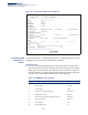
Table Of Contents
- How to Use This Guide
- Contents
- Figures
- Tables
- Getting Started
- Web Configuration
- Using the Web Interface
- Basic Management Tasks
- Displaying System Information
- Displaying Hardware/Software Versions
- Configuring Support for Jumbo Frames
- Displaying Bridge Extension Capabilities
- Managing System Files
- Setting the System Clock
- Configuring the Console Port
- Configuring Telnet Settings
- Displaying CPU Utilization
- Configuring CPU Guard
- Displaying Memory Utilization
- Resetting the System
- Interface Configuration
- VLAN Configuration
- Address Table Settings
- Spanning Tree Algorithm
- Congestion Control
- Class of Service
- Layer 2 Queue Settings
- Layer 3/4 Priority Settings
- Setting Priority Processing to IP Precedence/DSCP or CoS
- Mapping Ingress DSCP Values to Internal DSCP Values
- Mapping CoS Priorities to Internal DSCP Values
- Mapping Internal DSCP Values to Egress CoS Values
- Mapping IP Precedence Values to Internal DSCP Values
- Mapping IP Port Priority to Internal DSCP Values
- Quality of Service
- VoIP Traffic Configuration
- Security Measures
- AAA Authentication, Authorization and Accounting
- Configuring User Accounts
- Web Authentication
- Network Access (MAC Address Authentication)
- Configuring HTTPS
- Configuring the Secure Shell
- Access Control Lists
- Filtering IP Addresses for Management Access
- Configuring Port Security
- Configuring 802.1X Port Authentication
- DoS Protection
- DHCPv4 Snooping
- DHCPv6 Snooping
- IPv4 Source Guard
- IPv6 Source Guard
- ARP Inspection
- Application Filter
- Basic Administration Protocols
- Configuring Event Logging
- Link Layer Discovery Protocol
- Simple Network Management Protocol
- Configuring Global Settings for SNMP
- Setting Community Access Strings
- Setting the Local Engine ID
- Specifying a Remote Engine ID
- Setting SNMPv3 Views
- Configuring SNMPv3 Groups
- Configuring Local SNMPv3 Users
- Configuring Remote SNMPv3 Users
- Specifying Trap Managers
- Creating SNMP Notification Logs
- Showing SNMP Statistics
- Remote Monitoring
- Switch Clustering
- Setting a Time Range
- Ethernet Ring Protection Switching
- OAM Configuration
- Connectivity Fault Management
- Configuring Global Settings for CFM
- Configuring Interfaces for CFM
- Configuring CFM Maintenance Domains
- Configuring CFM Maintenance Associations
- Configuring Maintenance End Points
- Configuring Remote Maintenance End Points
- Transmitting Link Trace Messages
- Transmitting Loop Back Messages
- Transmitting Delay-Measure Requests
- Displaying Local MEPs
- Displaying Details for Local MEPs
- Displaying Local MIPs
- Displaying Remote MEPs
- Displaying Details for Remote MEPs
- Displaying the Link Trace Cache
- Displaying Fault Notification Settings
- Displaying Continuity Check Errors
- OAM Configuration
- UDLD Configuration
- LBD Configuration
- Smart Pair Configuration
- Multicast Filtering
- Overview
- Layer 2 IGMP (Snooping and Query for IPv4)
- Configuring IGMP Snooping and Query Parameters
- Specifying Static Interfaces for a Multicast Router
- Assigning Interfaces to Multicast Services
- Setting IGMP Snooping Status per Interface
- Filtering IGMP Query Packets and Multicast Data
- Displaying Multicast Groups Discovered by IGMP Snooping
- Displaying IGMP Snooping Statistics
- Filtering and Throttling IGMP Groups
- MLD Snooping (Snooping and Query for IPv6)
- Multicast VLAN Registration for IPv4
- Multicast VLAN Registration for IPv6
- Basic IP Functions
- IP Configuration
- General IP Routing
- IP Services
- Appendices
- Glossary

Chapter 13
| Basic Administration Protocols
Link Layer Discovery Protocol
– 417 –
b. If both the management-ipv6-address and the IPv6 address of a VLAN
interface are configured, the IPv6 address of the VLAN ID will be sent in the
Management Address TLV of the LLDP PDU transmitted.
c. Two Management Address TLVs in the LLDP PDU will be sent if both of the
two conditions below are true:
■
The interface has both commands configured i.e. management-ip-
address and management-ipv6-address.
■
The VLAN interface has both IPv4 and IPv6 addresses set.
One management address TLV will be the IPv4 address and the other will
be the IPv6 address.
d. The CPU MAC address (or device MAC address) will be sent in the
Management Address TLV of the LLDP PDU transmitted if the following two
configuration conditions are met:
■
Either or both the management-ip-address or management-ipv6-
address are configured
Neither the IPv4 address nor the IPv6 address of a VLAN interface is
configured.
■
Port Description – The port description is taken from the ifDescr object in
RFC 2863, which includes information about the manufacturer, the product
name, and the version of the interface hardware/software.
(Default: Enabled)
■
System Capabilities – The system capabilities identifies the primary
function(s) of the system and whether or not these primary functions are
enabled. The information advertised by this TLV is described in IEEE
802.1AB. (Default: Enabled)
■
System Description – The system description is taken from the sysDescr
object in RFC 3418, which includes the full name and version identification
of the system's hardware type, software operating system, and networking
software. (Default: Enabled)
■
System Name – The system name is taken from the sysName object in
RFC 3418, which contains the system’s administratively assigned name. To
configure the system name, see “Displaying System Information” on
page 78. (Default: Enabled)
◆ 802.1 Organizationally Specific TLVs – Configures IEEE 802.1 information
included in the TLV field of advertised messages.
■
Protocol Identity – The protocols that are accessible through this interface
(see “Protocol VLANs” on page 193). (Default: Enabled)