
Web Management Guide-R04

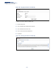
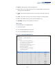
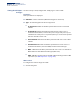
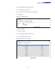
Table Of Contents
- How to Use This Guide
- Contents
- Figures
- Tables
- Getting Started
- Web Configuration
- Using the Web Interface
- Basic Management Tasks
- Displaying System Information
- Displaying Hardware/Software Versions
- Configuring Support for Jumbo Frames
- Displaying Bridge Extension Capabilities
- Managing System Files
- Setting the System Clock
- Configuring the Console Port
- Configuring Telnet Settings
- Displaying CPU Utilization
- Configuring CPU Guard
- Displaying Memory Utilization
- Resetting the System
- Interface Configuration
- VLAN Configuration
- Address Table Settings
- Spanning Tree Algorithm
- Congestion Control
- Class of Service
- Layer 2 Queue Settings
- Layer 3/4 Priority Settings
- Setting Priority Processing to IP Precedence/DSCP or CoS
- Mapping Ingress DSCP Values to Internal DSCP Values
- Mapping CoS Priorities to Internal DSCP Values
- Mapping Internal DSCP Values to Egress CoS Values
- Mapping IP Precedence Values to Internal DSCP Values
- Mapping IP Port Priority to Internal DSCP Values
- Quality of Service
- VoIP Traffic Configuration
- Security Measures
- AAA Authentication, Authorization and Accounting
- Configuring User Accounts
- Web Authentication
- Network Access (MAC Address Authentication)
- Configuring HTTPS
- Configuring the Secure Shell
- Access Control Lists
- Filtering IP Addresses for Management Access
- Configuring Port Security
- Configuring 802.1X Port Authentication
- DoS Protection
- DHCPv4 Snooping
- DHCPv6 Snooping
- IPv4 Source Guard
- IPv6 Source Guard
- ARP Inspection
- Application Filter
- Basic Administration Protocols
- Configuring Event Logging
- Link Layer Discovery Protocol
- Simple Network Management Protocol
- Configuring Global Settings for SNMP
- Setting Community Access Strings
- Setting the Local Engine ID
- Specifying a Remote Engine ID
- Setting SNMPv3 Views
- Configuring SNMPv3 Groups
- Configuring Local SNMPv3 Users
- Configuring Remote SNMPv3 Users
- Specifying Trap Managers
- Creating SNMP Notification Logs
- Showing SNMP Statistics
- Remote Monitoring
- Switch Clustering
- Setting a Time Range
- Ethernet Ring Protection Switching
- OAM Configuration
- Connectivity Fault Management
- Configuring Global Settings for CFM
- Configuring Interfaces for CFM
- Configuring CFM Maintenance Domains
- Configuring CFM Maintenance Associations
- Configuring Maintenance End Points
- Configuring Remote Maintenance End Points
- Transmitting Link Trace Messages
- Transmitting Loop Back Messages
- Transmitting Delay-Measure Requests
- Displaying Local MEPs
- Displaying Details for Local MEPs
- Displaying Local MIPs
- Displaying Remote MEPs
- Displaying Details for Remote MEPs
- Displaying the Link Trace Cache
- Displaying Fault Notification Settings
- Displaying Continuity Check Errors
- OAM Configuration
- UDLD Configuration
- LBD Configuration
- Smart Pair Configuration
- Multicast Filtering
- Overview
- Layer 2 IGMP (Snooping and Query for IPv4)
- Configuring IGMP Snooping and Query Parameters
- Specifying Static Interfaces for a Multicast Router
- Assigning Interfaces to Multicast Services
- Setting IGMP Snooping Status per Interface
- Filtering IGMP Query Packets and Multicast Data
- Displaying Multicast Groups Discovered by IGMP Snooping
- Displaying IGMP Snooping Statistics
- Filtering and Throttling IGMP Groups
- MLD Snooping (Snooping and Query for IPv6)
- Multicast VLAN Registration for IPv4
- Multicast VLAN Registration for IPv6
- Basic IP Functions
- IP Configuration
- General IP Routing
- IP Services
- Appendices
- Glossary

Chapter 12
| Security Measures
Access Control Lists
– 336 –
compression is disabled, the ACL would occupy (128*n) entries of TCAM, using
up nearly all of the hardware resources. When using compression, the 128 ACEs
are compressed into one ACE classifying the IP address as 192.168.1.0/24,
which requires only “n” entries in TCAM. The above example is an ideal case for
compression. The worst case would be if no any ACE can be compressed, in
which case the used number of TCAM entries would be the same as without
compression. It would also require more time to process the ACEs.
◆ If no matches are found down to the end of the list, the traffic is denied. For this
reason, frequently hit entries should be placed at the top of the list. There is an
implied deny for traffic that is not explicitly permitted. Also, note that a single-
entry ACL with only one deny entry has the effect of denying all traffic. You
should therefore use at least one permit statement in an ACL or all traffic will be
blocked.
Because the switch stops testing after the first match, the order of the
conditions is critical. If no conditions match, the packet will be denied.
The order in which active ACLs are checked is as follows:
1. User-defined rules in IP and MAC ACLs for ingress ports are checked in parallel.
2. Rules within an ACL are checked in the configured order, from top to bottom.
3. If the result of checking an IP ACL is to permit a packet, but the result of a MAC
ACL on the same packet is to deny it, the packet will be denied (because the
decision to deny a packet has a higher priority for security reasons). A packet
will also be denied if the IP ACL denies it and the MAC ACL accepts it.
Showing
TCAM Utilization
Use the Security > ACL (Configure ACL - Show TCAM) page to show utilization
parameters for TCAM (Ternary Content Addressable Memory), including the
number policy control entries in use, the number of free entries, and the overall
percentage of TCAM in use.
Command Usage
Policy control entries (PCEs) are used by various system functions which rely on
rule-based searches, including Access Control Lists (ACLs), IP Source Guard filter
rules, Quality of Service (QoS) processes, QinQ, MAC-based VLANs, VLAN
translation, or traps.
For example, when binding an ACL to a port, each rule in an ACL will use two PCEs;
and when setting an IP Source Guard filter rule for a port, the system will also use
two PCEs.
Parameters
These parameters are displayed:
◆ Pool Capability Code – Abbreviation for processes shown in the TCAM List.
◆ Unit – Stack unit identifier.