
Web Management Guide-R04
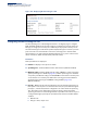
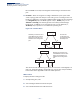
Table Of Contents
- How to Use This Guide
- Contents
- Figures
- Tables
- Getting Started
- Web Configuration
- Using the Web Interface
- Basic Management Tasks
- Displaying System Information
- Displaying Hardware/Software Versions
- Configuring Support for Jumbo Frames
- Displaying Bridge Extension Capabilities
- Managing System Files
- Setting the System Clock
- Configuring the Console Port
- Configuring Telnet Settings
- Displaying CPU Utilization
- Configuring CPU Guard
- Displaying Memory Utilization
- Resetting the System
- Interface Configuration
- VLAN Configuration
- Address Table Settings
- Spanning Tree Algorithm
- Congestion Control
- Class of Service
- Layer 2 Queue Settings
- Layer 3/4 Priority Settings
- Setting Priority Processing to IP Precedence/DSCP or CoS
- Mapping Ingress DSCP Values to Internal DSCP Values
- Mapping CoS Priorities to Internal DSCP Values
- Mapping Internal DSCP Values to Egress CoS Values
- Mapping IP Precedence Values to Internal DSCP Values
- Mapping IP Port Priority to Internal DSCP Values
- Quality of Service
- VoIP Traffic Configuration
- Security Measures
- AAA Authentication, Authorization and Accounting
- Configuring User Accounts
- Web Authentication
- Network Access (MAC Address Authentication)
- Configuring HTTPS
- Configuring the Secure Shell
- Access Control Lists
- Filtering IP Addresses for Management Access
- Configuring Port Security
- Configuring 802.1X Port Authentication
- DoS Protection
- DHCPv4 Snooping
- DHCPv6 Snooping
- IPv4 Source Guard
- IPv6 Source Guard
- ARP Inspection
- Application Filter
- Basic Administration Protocols
- Configuring Event Logging
- Link Layer Discovery Protocol
- Simple Network Management Protocol
- Configuring Global Settings for SNMP
- Setting Community Access Strings
- Setting the Local Engine ID
- Specifying a Remote Engine ID
- Setting SNMPv3 Views
- Configuring SNMPv3 Groups
- Configuring Local SNMPv3 Users
- Configuring Remote SNMPv3 Users
- Specifying Trap Managers
- Creating SNMP Notification Logs
- Showing SNMP Statistics
- Remote Monitoring
- Switch Clustering
- Setting a Time Range
- Ethernet Ring Protection Switching
- OAM Configuration
- Connectivity Fault Management
- Configuring Global Settings for CFM
- Configuring Interfaces for CFM
- Configuring CFM Maintenance Domains
- Configuring CFM Maintenance Associations
- Configuring Maintenance End Points
- Configuring Remote Maintenance End Points
- Transmitting Link Trace Messages
- Transmitting Loop Back Messages
- Transmitting Delay-Measure Requests
- Displaying Local MEPs
- Displaying Details for Local MEPs
- Displaying Local MIPs
- Displaying Remote MEPs
- Displaying Details for Remote MEPs
- Displaying the Link Trace Cache
- Displaying Fault Notification Settings
- Displaying Continuity Check Errors
- OAM Configuration
- UDLD Configuration
- LBD Configuration
- Smart Pair Configuration
- Multicast Filtering
- Overview
- Layer 2 IGMP (Snooping and Query for IPv4)
- Configuring IGMP Snooping and Query Parameters
- Specifying Static Interfaces for a Multicast Router
- Assigning Interfaces to Multicast Services
- Setting IGMP Snooping Status per Interface
- Filtering IGMP Query Packets and Multicast Data
- Displaying Multicast Groups Discovered by IGMP Snooping
- Displaying IGMP Snooping Statistics
- Filtering and Throttling IGMP Groups
- MLD Snooping (Snooping and Query for IPv6)
- Multicast VLAN Registration for IPv4
- Multicast VLAN Registration for IPv6
- Basic IP Functions
- IP Configuration
- General IP Routing
- IP Services
- Appendices
- Glossary

Chapter 7
| Spanning Tree Algorithm
Configuring Interface Settings for STA
– 226 –
The root path cost for i1 on SW3 used to compete for the role of root port is
0 + path cost of i1 on SW3; 0 since i1 is directly connected to the root bridge.
If the path cost of i1 on SW2 is never configured/changed, it is 10000.
Then the root path cost for i2 on SW3 used to compete for the role of root port
is 10000 + path cost of i2 on SW3.
The path cost of i1 on SW3 is also 10000 if not configured/changed.
Then even if the path cost of i2 on SW3 is configured/changed to 0, these ports
will still have the same root path cost, and it will be impossible for i2 to become
the root port just by changing its path cost on SW3.
For RSTP mode, the root port can be determined simply by adjusting the path
cost of i1 on SW2. However, for MSTP mode, it is impossible to achieve this only
by changing the path cost because external path cost is not added in the same
region, and the regional root for i1 is SW1, but for i2 is SW2.
◆ Admin Link Type – The link type attached to this interface.
■
Point-to-Point – A connection to exactly one other bridge.
■
Shared – A connection to two or more bridges.
■
Auto – The switch automatically determines if the interface is attached to a
point-to-point link or to shared media. (This is the default setting.)
◆ Root Guard – STA allows a bridge with a lower bridge identifier (or same
identifier and lower MAC address) to take over as the root bridge at any time.
Root Guard can be used to ensure that the root bridge is not formed at a
suboptimal location. Root Guard should be enabled on any designated port
connected to low-speed bridges which could potentially overload a slower link
by taking over as the root port and forming a new spanning tree topology. It
could also
be used to form a border around part of the network where the root
bridge is allowed. (Default: Disabled)
◆ Admin Edge Port – Since end nodes cannot cause forwarding loops, they can
pass directly through to the spanning tree forwarding state. Specifying Edge
Ports provides quicker convergence for devices such as workstations or servers,
retains the current forwarding database to reduce the amount of frame
flooding required to rebuild address tables during reconfiguration events, does
not cause the spanning tree to initiate reconfiguration when the interface
changes state, and also overcomes other STA-related timeout problems.
However, remember that Edge Port should only be enabled for ports
connected to an end-node device. (Default: Auto)
■
Enabled – Manually configures a port as an Edge Port.
■
Disabled – Disables the Edge Port setting.
■
Auto – The port will be automatically configured as an edge port if the
edge delay time expires without receiving any RSTP or MSTP BPDUs. Note
that edge delay time (802.1D-2004 17.20.4) equals the protocol migration
time if a port's link type is point-to-point (which is 3 seconds as defined in