
Web Management Guide-R04
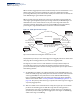
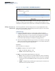
Table Of Contents
- How to Use This Guide
- Contents
- Figures
- Tables
- Getting Started
- Web Configuration
- Using the Web Interface
- Basic Management Tasks
- Displaying System Information
- Displaying Hardware/Software Versions
- Configuring Support for Jumbo Frames
- Displaying Bridge Extension Capabilities
- Managing System Files
- Setting the System Clock
- Configuring the Console Port
- Configuring Telnet Settings
- Displaying CPU Utilization
- Configuring CPU Guard
- Displaying Memory Utilization
- Resetting the System
- Interface Configuration
- VLAN Configuration
- Address Table Settings
- Spanning Tree Algorithm
- Congestion Control
- Class of Service
- Layer 2 Queue Settings
- Layer 3/4 Priority Settings
- Setting Priority Processing to IP Precedence/DSCP or CoS
- Mapping Ingress DSCP Values to Internal DSCP Values
- Mapping CoS Priorities to Internal DSCP Values
- Mapping Internal DSCP Values to Egress CoS Values
- Mapping IP Precedence Values to Internal DSCP Values
- Mapping IP Port Priority to Internal DSCP Values
- Quality of Service
- VoIP Traffic Configuration
- Security Measures
- AAA Authentication, Authorization and Accounting
- Configuring User Accounts
- Web Authentication
- Network Access (MAC Address Authentication)
- Configuring HTTPS
- Configuring the Secure Shell
- Access Control Lists
- Filtering IP Addresses for Management Access
- Configuring Port Security
- Configuring 802.1X Port Authentication
- DoS Protection
- DHCPv4 Snooping
- DHCPv6 Snooping
- IPv4 Source Guard
- IPv6 Source Guard
- ARP Inspection
- Application Filter
- Basic Administration Protocols
- Configuring Event Logging
- Link Layer Discovery Protocol
- Simple Network Management Protocol
- Configuring Global Settings for SNMP
- Setting Community Access Strings
- Setting the Local Engine ID
- Specifying a Remote Engine ID
- Setting SNMPv3 Views
- Configuring SNMPv3 Groups
- Configuring Local SNMPv3 Users
- Configuring Remote SNMPv3 Users
- Specifying Trap Managers
- Creating SNMP Notification Logs
- Showing SNMP Statistics
- Remote Monitoring
- Switch Clustering
- Setting a Time Range
- Ethernet Ring Protection Switching
- OAM Configuration
- Connectivity Fault Management
- Configuring Global Settings for CFM
- Configuring Interfaces for CFM
- Configuring CFM Maintenance Domains
- Configuring CFM Maintenance Associations
- Configuring Maintenance End Points
- Configuring Remote Maintenance End Points
- Transmitting Link Trace Messages
- Transmitting Loop Back Messages
- Transmitting Delay-Measure Requests
- Displaying Local MEPs
- Displaying Details for Local MEPs
- Displaying Local MIPs
- Displaying Remote MEPs
- Displaying Details for Remote MEPs
- Displaying the Link Trace Cache
- Displaying Fault Notification Settings
- Displaying Continuity Check Errors
- OAM Configuration
- UDLD Configuration
- LBD Configuration
- Smart Pair Configuration
- Multicast Filtering
- Overview
- Layer 2 IGMP (Snooping and Query for IPv4)
- Configuring IGMP Snooping and Query Parameters
- Specifying Static Interfaces for a Multicast Router
- Assigning Interfaces to Multicast Services
- Setting IGMP Snooping Status per Interface
- Filtering IGMP Query Packets and Multicast Data
- Displaying Multicast Groups Discovered by IGMP Snooping
- Displaying IGMP Snooping Statistics
- Filtering and Throttling IGMP Groups
- MLD Snooping (Snooping and Query for IPv6)
- Multicast VLAN Registration for IPv4
- Multicast VLAN Registration for IPv6
- Basic IP Functions
- IP Configuration
- General IP Routing
- IP Services
- Appendices
- Glossary

Chapter 5
| VLAN Configuration
IEEE 802.1Q Tunneling
– 184 –
6. After packet classification, the packet is written to memory for processing as a
single-tagged or double-tagged packet.
7. The switch sends the packet to the proper egress port.
8. If the egress port is an untagged member of the SPVLAN, the outer tag will be
stripped. If it is a tagged member, the outgoing packet will have two tags.
Configuration Limitations for QinQ
◆ The native VLAN of uplink ports should not be used as the SPVLAN. If the
SPVLAN is the uplink port's native VLAN, the uplink port must be an untagged
member of the SPVLAN. Then the outer SPVLAN tag will be stripped when the
packets are sent out. Another reason is that it causes non-customer packets to
be forwarded to the SPVLAN.
◆ Static trunk port groups are compatible with QinQ tunnel ports as long as the
QinQ configuration is consistent within a trunk port group.
◆ The native VLAN (VLAN 1) is not normally added to transmitted frames. Avoid
using VLAN 1 as an SPVLAN tag for customer traffic to reduce the risk of
misconfiguration. Instead, use VLAN 1 as a management VLAN instead of a data
VLAN in the service provider network.
◆ There are some inherent incompatibilities between Layer 2 and Layer 3
switching:
■
Tunnel ports do not support IP Access Control Lists.
■
Layer 3 Quality of Service (QoS) and other QoS features containing Layer 3
information are not supported on tunnel ports.
■
Spanning tree bridge protocol data unit (BPDU) filtering is automatically
disabled on a tunnel port.
General Configuration Guidelines for QinQ
1. Enable Tunnel Status, and set the Tag Protocol Identifier (TPID) value of the
tunnel access port (in the Ethernet Type field). This step is required if the
attached client is using a nonstandard 2-byte ethertype to identify 802.1Q
tagged frames. The default ethertype value is 0x8100. (See “Enabling QinQ
Tunneling on the Switch” on page 185.)
2. Create a Service Provider VLAN, also referred to as an SPVLAN (see “Configuring
VLAN Groups” on page 171).
3. Configure the QinQ tunnel access port to Access mode (see “Adding an
Interface to QinQ Tunnel” on page 188).
4. Configure the QinQ tunnel access port to join the SPVLAN as an untagged
member (see “Adding Static Members to VLANs” on page 173).