
Web Management Guide-R04
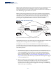
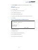
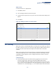
Table Of Contents
- How to Use This Guide
- Contents
- Figures
- Tables
- Getting Started
- Web Configuration
- Using the Web Interface
- Basic Management Tasks
- Displaying System Information
- Displaying Hardware/Software Versions
- Configuring Support for Jumbo Frames
- Displaying Bridge Extension Capabilities
- Managing System Files
- Setting the System Clock
- Configuring the Console Port
- Configuring Telnet Settings
- Displaying CPU Utilization
- Configuring CPU Guard
- Displaying Memory Utilization
- Resetting the System
- Interface Configuration
- VLAN Configuration
- Address Table Settings
- Spanning Tree Algorithm
- Congestion Control
- Class of Service
- Layer 2 Queue Settings
- Layer 3/4 Priority Settings
- Setting Priority Processing to IP Precedence/DSCP or CoS
- Mapping Ingress DSCP Values to Internal DSCP Values
- Mapping CoS Priorities to Internal DSCP Values
- Mapping Internal DSCP Values to Egress CoS Values
- Mapping IP Precedence Values to Internal DSCP Values
- Mapping IP Port Priority to Internal DSCP Values
- Quality of Service
- VoIP Traffic Configuration
- Security Measures
- AAA Authentication, Authorization and Accounting
- Configuring User Accounts
- Web Authentication
- Network Access (MAC Address Authentication)
- Configuring HTTPS
- Configuring the Secure Shell
- Access Control Lists
- Filtering IP Addresses for Management Access
- Configuring Port Security
- Configuring 802.1X Port Authentication
- DoS Protection
- DHCPv4 Snooping
- DHCPv6 Snooping
- IPv4 Source Guard
- IPv6 Source Guard
- ARP Inspection
- Application Filter
- Basic Administration Protocols
- Configuring Event Logging
- Link Layer Discovery Protocol
- Simple Network Management Protocol
- Configuring Global Settings for SNMP
- Setting Community Access Strings
- Setting the Local Engine ID
- Specifying a Remote Engine ID
- Setting SNMPv3 Views
- Configuring SNMPv3 Groups
- Configuring Local SNMPv3 Users
- Configuring Remote SNMPv3 Users
- Specifying Trap Managers
- Creating SNMP Notification Logs
- Showing SNMP Statistics
- Remote Monitoring
- Switch Clustering
- Setting a Time Range
- Ethernet Ring Protection Switching
- OAM Configuration
- Connectivity Fault Management
- Configuring Global Settings for CFM
- Configuring Interfaces for CFM
- Configuring CFM Maintenance Domains
- Configuring CFM Maintenance Associations
- Configuring Maintenance End Points
- Configuring Remote Maintenance End Points
- Transmitting Link Trace Messages
- Transmitting Loop Back Messages
- Transmitting Delay-Measure Requests
- Displaying Local MEPs
- Displaying Details for Local MEPs
- Displaying Local MIPs
- Displaying Remote MEPs
- Displaying Details for Remote MEPs
- Displaying the Link Trace Cache
- Displaying Fault Notification Settings
- Displaying Continuity Check Errors
- OAM Configuration
- UDLD Configuration
- LBD Configuration
- Smart Pair Configuration
- Multicast Filtering
- Overview
- Layer 2 IGMP (Snooping and Query for IPv4)
- Configuring IGMP Snooping and Query Parameters
- Specifying Static Interfaces for a Multicast Router
- Assigning Interfaces to Multicast Services
- Setting IGMP Snooping Status per Interface
- Filtering IGMP Query Packets and Multicast Data
- Displaying Multicast Groups Discovered by IGMP Snooping
- Displaying IGMP Snooping Statistics
- Filtering and Throttling IGMP Groups
- MLD Snooping (Snooping and Query for IPv6)
- Multicast VLAN Registration for IPv4
- Multicast VLAN Registration for IPv6
- Basic IP Functions
- IP Configuration
- General IP Routing
- IP Services
- Appendices
- Glossary

Chapter 5
| VLAN Configuration
IEEE 802.1Q Tunneling
– 181 –
Figure 90: Showing the Members of a Dynamic VLAN
IEEE 802.1Q Tunneling
IEEE 802.1Q Tunneling (QinQ) is designed for service providers carrying traffic for
multiple customers across their networks. QinQ tunneling is used to maintain
customer-specific VLAN and Layer 2 protocol configurations even when different
customers use the same internal VLAN IDs. This is accomplished by inserting
Service Provider VLAN (SPVLAN) tags into the customer’s frames when they enter
the service provider’s network, and then stripping the tags when the frames leave
the network.
A service provider’s customers may have specific requirements for their internal
VLAN IDs and number of VLANs supported. VLAN ranges required by different
customers in the same service-provider network might easily overlap, and traffic
passing through the infrastructure might be mixed. Assigning a unique range of
VLAN IDs to each customer would restrict customer configurations, require
intensive processing of VLAN mapping tables, and could easily exceed the
maximum VLAN limit of 4096.
QinQ tunneling uses a single Service Provider VLAN (SPVLAN) for customers who
have multiple VLANs. Customer VLAN IDs are preserved and traffic from different
customers is segregated within the service provider’s network even when they use
the same customer-specific VLAN IDs. QinQ tunneling expands VLAN space by
using a VLAN-in-VLAN hierarchy, preserving the customer’s original tagged
packets, and adding SPVLAN tags to each frame (also called double tagging).
A port configured to support QinQ tunneling must be set to tunnel port mode. The
Service Provider VLAN (SPVLAN) ID for the specific customer must be assigned to
the QinQ tunnel access port on the edge switch where the customer traffic enters
the service provider’s network. Each customer requires a separate SPVLAN, but this
VLAN supports all of the customer's internal VLANs. The QinQ tunnel uplink port
that passes traffic from the edge switch into the service provider’s metro network
must also be added to this SPVLAN. The uplink port can be added to multiple
SPVLANs to carry inbound traffic for different customers onto the service provider’s
network.