
Web Management Guide-R04
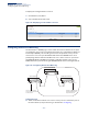
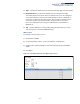
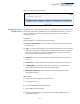
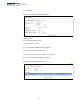
Table Of Contents
- How to Use This Guide
- Contents
- Figures
- Tables
- Getting Started
- Web Configuration
- Using the Web Interface
- Basic Management Tasks
- Displaying System Information
- Displaying Hardware/Software Versions
- Configuring Support for Jumbo Frames
- Displaying Bridge Extension Capabilities
- Managing System Files
- Setting the System Clock
- Configuring the Console Port
- Configuring Telnet Settings
- Displaying CPU Utilization
- Configuring CPU Guard
- Displaying Memory Utilization
- Resetting the System
- Interface Configuration
- VLAN Configuration
- Address Table Settings
- Spanning Tree Algorithm
- Congestion Control
- Class of Service
- Layer 2 Queue Settings
- Layer 3/4 Priority Settings
- Setting Priority Processing to IP Precedence/DSCP or CoS
- Mapping Ingress DSCP Values to Internal DSCP Values
- Mapping CoS Priorities to Internal DSCP Values
- Mapping Internal DSCP Values to Egress CoS Values
- Mapping IP Precedence Values to Internal DSCP Values
- Mapping IP Port Priority to Internal DSCP Values
- Quality of Service
- VoIP Traffic Configuration
- Security Measures
- AAA Authentication, Authorization and Accounting
- Configuring User Accounts
- Web Authentication
- Network Access (MAC Address Authentication)
- Configuring HTTPS
- Configuring the Secure Shell
- Access Control Lists
- Filtering IP Addresses for Management Access
- Configuring Port Security
- Configuring 802.1X Port Authentication
- DoS Protection
- DHCPv4 Snooping
- DHCPv6 Snooping
- IPv4 Source Guard
- IPv6 Source Guard
- ARP Inspection
- Application Filter
- Basic Administration Protocols
- Configuring Event Logging
- Link Layer Discovery Protocol
- Simple Network Management Protocol
- Configuring Global Settings for SNMP
- Setting Community Access Strings
- Setting the Local Engine ID
- Specifying a Remote Engine ID
- Setting SNMPv3 Views
- Configuring SNMPv3 Groups
- Configuring Local SNMPv3 Users
- Configuring Remote SNMPv3 Users
- Specifying Trap Managers
- Creating SNMP Notification Logs
- Showing SNMP Statistics
- Remote Monitoring
- Switch Clustering
- Setting a Time Range
- Ethernet Ring Protection Switching
- OAM Configuration
- Connectivity Fault Management
- Configuring Global Settings for CFM
- Configuring Interfaces for CFM
- Configuring CFM Maintenance Domains
- Configuring CFM Maintenance Associations
- Configuring Maintenance End Points
- Configuring Remote Maintenance End Points
- Transmitting Link Trace Messages
- Transmitting Loop Back Messages
- Transmitting Delay-Measure Requests
- Displaying Local MEPs
- Displaying Details for Local MEPs
- Displaying Local MIPs
- Displaying Remote MEPs
- Displaying Details for Remote MEPs
- Displaying the Link Trace Cache
- Displaying Fault Notification Settings
- Displaying Continuity Check Errors
- OAM Configuration
- UDLD Configuration
- LBD Configuration
- Smart Pair Configuration
- Multicast Filtering
- Overview
- Layer 2 IGMP (Snooping and Query for IPv4)
- Configuring IGMP Snooping and Query Parameters
- Specifying Static Interfaces for a Multicast Router
- Assigning Interfaces to Multicast Services
- Setting IGMP Snooping Status per Interface
- Filtering IGMP Query Packets and Multicast Data
- Displaying Multicast Groups Discovered by IGMP Snooping
- Displaying IGMP Snooping Statistics
- Filtering and Throttling IGMP Groups
- MLD Snooping (Snooping and Query for IPv6)
- Multicast VLAN Registration for IPv4
- Multicast VLAN Registration for IPv6
- Basic IP Functions
- IP Configuration
- General IP Routing
- IP Services
- Appendices
- Glossary

Chapter 4
| Interface Configuration
Sampling Traffic Flows
– 157 –
Note:
The terms “collector”, “receiver” and “owner”, in the context of this chapter, all
refer to a remote server capable of receiving the sFlow datagrams generated by the
sFlow agent of the switch.
As the Collector receives streams from the various sFlow agents (other switches or
routers) throughout the network, a timely, network-wide picture of utilization and
traffic flows is created. Analysis of the sFlow stream(s) can reveal trends and
information that can be leveraged in the following ways:
◆ Detecting, diagnosing, and fixing network problems
◆ Real-time congestion management
◆ Understanding application mix (P2P, Web, DNS, etc.) and changes
◆ Identification and tracing of unauthorized network activity
◆ Usage accounting
◆ Trending and capacity planning
Configuring sFlow
Receiver Settings
Use the Interface > sFlow (Configure Receiver – Add) page to create an sFlow
receiver on the switch.
Parameters
These parameters are displayed:
◆ Receiver Owner Name
7
– The name of the receiver. (Range: 1-256 characters;
Default: None)
◆ Receiver Timeout – The time that the sFlow process will continuously send
samples to the Collector before resetting all sFlow port parameters.
(Range: 30-10000000 seconds, where 0 indicates no time out)
The sFlow parameters affected by this command include the sampling interval,
the receiver’s name, address and UDP port, the time out, maximum header size,
and maximum datagram size.
◆ Receiver Destination
7
– IP address of the sFlow Collector.
■
ipv4-address - IPv4 address of the sFlow collector. Valid IPv4 addresses
consist of four decimal numbers, 0 to 255, separated by periods.
■
ipv6-address - IPv6 address of the sFlow collector. A full IPv6 address
including the network prefix and host address bits. An IPv6 address consists
of 8 colon-separated 16-bit hexadecimal values. One double colon may be
7. Sampling must be disabled by setting the time out to 0 before these fields can be
configured.