
Web Management Guide-R04
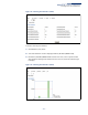
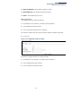
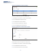
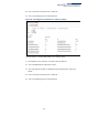
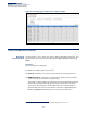
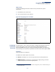
Table Of Contents
- How to Use This Guide
- Contents
- Figures
- Tables
- Getting Started
- Web Configuration
- Using the Web Interface
- Basic Management Tasks
- Displaying System Information
- Displaying Hardware/Software Versions
- Configuring Support for Jumbo Frames
- Displaying Bridge Extension Capabilities
- Managing System Files
- Setting the System Clock
- Configuring the Console Port
- Configuring Telnet Settings
- Displaying CPU Utilization
- Configuring CPU Guard
- Displaying Memory Utilization
- Resetting the System
- Interface Configuration
- VLAN Configuration
- Address Table Settings
- Spanning Tree Algorithm
- Congestion Control
- Class of Service
- Layer 2 Queue Settings
- Layer 3/4 Priority Settings
- Setting Priority Processing to IP Precedence/DSCP or CoS
- Mapping Ingress DSCP Values to Internal DSCP Values
- Mapping CoS Priorities to Internal DSCP Values
- Mapping Internal DSCP Values to Egress CoS Values
- Mapping IP Precedence Values to Internal DSCP Values
- Mapping IP Port Priority to Internal DSCP Values
- Quality of Service
- VoIP Traffic Configuration
- Security Measures
- AAA Authentication, Authorization and Accounting
- Configuring User Accounts
- Web Authentication
- Network Access (MAC Address Authentication)
- Configuring HTTPS
- Configuring the Secure Shell
- Access Control Lists
- Filtering IP Addresses for Management Access
- Configuring Port Security
- Configuring 802.1X Port Authentication
- DoS Protection
- DHCPv4 Snooping
- DHCPv6 Snooping
- IPv4 Source Guard
- IPv6 Source Guard
- ARP Inspection
- Application Filter
- Basic Administration Protocols
- Configuring Event Logging
- Link Layer Discovery Protocol
- Simple Network Management Protocol
- Configuring Global Settings for SNMP
- Setting Community Access Strings
- Setting the Local Engine ID
- Specifying a Remote Engine ID
- Setting SNMPv3 Views
- Configuring SNMPv3 Groups
- Configuring Local SNMPv3 Users
- Configuring Remote SNMPv3 Users
- Specifying Trap Managers
- Creating SNMP Notification Logs
- Showing SNMP Statistics
- Remote Monitoring
- Switch Clustering
- Setting a Time Range
- Ethernet Ring Protection Switching
- OAM Configuration
- Connectivity Fault Management
- Configuring Global Settings for CFM
- Configuring Interfaces for CFM
- Configuring CFM Maintenance Domains
- Configuring CFM Maintenance Associations
- Configuring Maintenance End Points
- Configuring Remote Maintenance End Points
- Transmitting Link Trace Messages
- Transmitting Loop Back Messages
- Transmitting Delay-Measure Requests
- Displaying Local MEPs
- Displaying Details for Local MEPs
- Displaying Local MIPs
- Displaying Remote MEPs
- Displaying Details for Remote MEPs
- Displaying the Link Trace Cache
- Displaying Fault Notification Settings
- Displaying Continuity Check Errors
- OAM Configuration
- UDLD Configuration
- LBD Configuration
- Smart Pair Configuration
- Multicast Filtering
- Overview
- Layer 2 IGMP (Snooping and Query for IPv4)
- Configuring IGMP Snooping and Query Parameters
- Specifying Static Interfaces for a Multicast Router
- Assigning Interfaces to Multicast Services
- Setting IGMP Snooping Status per Interface
- Filtering IGMP Query Packets and Multicast Data
- Displaying Multicast Groups Discovered by IGMP Snooping
- Displaying IGMP Snooping Statistics
- Filtering and Throttling IGMP Groups
- MLD Snooping (Snooping and Query for IPv6)
- Multicast VLAN Registration for IPv4
- Multicast VLAN Registration for IPv6
- Basic IP Functions
- IP Configuration
- General IP Routing
- IP Services
- Appendices
- Glossary

Chapter 4
| Interface Configuration
Transceiver Data and Thresholds
– 130 –
The switch can display diagnostic information for SFP modules which support
the SFF-8472 Specification for Diagnostic Monitoring Interface for Optical
Transceivers. This information allows administrators to remotely diagnose
problems with optical devices. This feature, referred to as Digital Diagnostic
Monitoring (DDM) provides information on transceiver parameters.
◆ Trap – Sends a trap when any of the transceiver’s operation values falls outside
of specified thresholds. (Default: Disabled)
◆ Auto Mode – Uses default threshold settings obtained from the transceiver to
determine when an alarm or trap message should be sent. (Default: Enabled)
◆ DDM Thresholds – Information on alarm and warning thresholds. The switch
can be configured to send a trap when the measured parameter falls outside of
the specified thresholds.
The following alarm and warning parameters are supported:
■
High Alarm – Sends an alarm message when the high threshold is crossed.
■
High Warning – Sends a warning message when the high threshold is
crossed.
■
Low Warning – Sends a warning message when the low threshold is
crossed.
■
Low Alarm – Sends an alarm message when the low threshold is crossed.
The configurable ranges are:
■
Tempe rat ure: -128.00-128.00 °C
■
Voltage: 0.00-6.55 Volts
■
Current: 0.00-131.00 mA
■
Power: -40.00-8.20 dBm
The threshold value for Rx and Tx power is calculated as the power ratio in
decibels (dB) of the measured power referenced to one milliwatt (mW).
Threshold values for alarm and warning messages can be configured as
described below.
■
A high-threshold alarm or warning message is sent if the current value is
greater than or equal to the threshold, and the last sample value was less
than the threshold. After a rising event has been generated, another such
event will not be generated until the sampled value has fallen below the
high threshold and reaches the low threshold.
■
A low-threshold alarm or warning message is sent if the current value is less
than or equal to the threshold, and the last sample value was greater than
the threshold. After a falling event has been generated, another such event
will not be generated until the sampled value has risen above the low
threshold and reaches the high threshold.