
Web Management Guide-R04

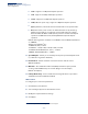
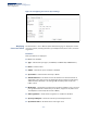
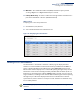
Table Of Contents
- How to Use This Guide
- Contents
- Figures
- Tables
- Getting Started
- Web Configuration
- Using the Web Interface
- Basic Management Tasks
- Displaying System Information
- Displaying Hardware/Software Versions
- Configuring Support for Jumbo Frames
- Displaying Bridge Extension Capabilities
- Managing System Files
- Setting the System Clock
- Configuring the Console Port
- Configuring Telnet Settings
- Displaying CPU Utilization
- Configuring CPU Guard
- Displaying Memory Utilization
- Resetting the System
- Interface Configuration
- VLAN Configuration
- Address Table Settings
- Spanning Tree Algorithm
- Congestion Control
- Class of Service
- Layer 2 Queue Settings
- Layer 3/4 Priority Settings
- Setting Priority Processing to IP Precedence/DSCP or CoS
- Mapping Ingress DSCP Values to Internal DSCP Values
- Mapping CoS Priorities to Internal DSCP Values
- Mapping Internal DSCP Values to Egress CoS Values
- Mapping IP Precedence Values to Internal DSCP Values
- Mapping IP Port Priority to Internal DSCP Values
- Quality of Service
- VoIP Traffic Configuration
- Security Measures
- AAA Authentication, Authorization and Accounting
- Configuring User Accounts
- Web Authentication
- Network Access (MAC Address Authentication)
- Configuring HTTPS
- Configuring the Secure Shell
- Access Control Lists
- Filtering IP Addresses for Management Access
- Configuring Port Security
- Configuring 802.1X Port Authentication
- DoS Protection
- DHCPv4 Snooping
- DHCPv6 Snooping
- IPv4 Source Guard
- IPv6 Source Guard
- ARP Inspection
- Application Filter
- Basic Administration Protocols
- Configuring Event Logging
- Link Layer Discovery Protocol
- Simple Network Management Protocol
- Configuring Global Settings for SNMP
- Setting Community Access Strings
- Setting the Local Engine ID
- Specifying a Remote Engine ID
- Setting SNMPv3 Views
- Configuring SNMPv3 Groups
- Configuring Local SNMPv3 Users
- Configuring Remote SNMPv3 Users
- Specifying Trap Managers
- Creating SNMP Notification Logs
- Showing SNMP Statistics
- Remote Monitoring
- Switch Clustering
- Setting a Time Range
- Ethernet Ring Protection Switching
- OAM Configuration
- Connectivity Fault Management
- Configuring Global Settings for CFM
- Configuring Interfaces for CFM
- Configuring CFM Maintenance Domains
- Configuring CFM Maintenance Associations
- Configuring Maintenance End Points
- Configuring Remote Maintenance End Points
- Transmitting Link Trace Messages
- Transmitting Loop Back Messages
- Transmitting Delay-Measure Requests
- Displaying Local MEPs
- Displaying Details for Local MEPs
- Displaying Local MIPs
- Displaying Remote MEPs
- Displaying Details for Remote MEPs
- Displaying the Link Trace Cache
- Displaying Fault Notification Settings
- Displaying Continuity Check Errors
- OAM Configuration
- UDLD Configuration
- LBD Configuration
- Smart Pair Configuration
- Multicast Filtering
- Overview
- Layer 2 IGMP (Snooping and Query for IPv4)
- Configuring IGMP Snooping and Query Parameters
- Specifying Static Interfaces for a Multicast Router
- Assigning Interfaces to Multicast Services
- Setting IGMP Snooping Status per Interface
- Filtering IGMP Query Packets and Multicast Data
- Displaying Multicast Groups Discovered by IGMP Snooping
- Displaying IGMP Snooping Statistics
- Filtering and Throttling IGMP Groups
- MLD Snooping (Snooping and Query for IPv6)
- Multicast VLAN Registration for IPv4
- Multicast VLAN Registration for IPv6
- Basic IP Functions
- IP Configuration
- General IP Routing
- IP Services
- Appendices
- Glossary

Chapter 4
| Interface Configuration
Port Configuration
– 115 –
◆ For other traffic types, calculation of overall frame size is basically the same,
including the additional header fields SA(6) + DA(6) + Type(2) + VLAN-Tag(4) for
tagged packets, (for untaqged packets, the 4-byte field will not be added by
switch), and the payload. This should all be less than the configured port MTU,
including the CRC at the end of the frame.
◆ For QinQ, the overall frame size is still calculated as described above, but does
not add the length of the second tag to the frame.
Parameters
These parameters are displayed:
◆ Port – Port identifier. (Range: 1-28)
◆ Type – Indicates the port type. (1000BASE-T, 100BASE-FX SFP, 1000BASE SFP,
10GBASE SFP+)
◆ Name – Allows you to label an interface. (Range: 1-64 characters)
◆ Admin – Allows you to manually disable an interface. You can disable an
interface due to abnormal behavior (e.g., excessive collisions), and then re-
enable it after the problem has been resolved. You may also disable an
interface for security reasons. (Default: Enabled)
◆ Media Type – Configures forced transceiver mode for SFP/SFP+ ports, or
forced/preferred port type for RJ-45/SFP combination ports
.
■
None - Forced transceiver mode is not used for SFP/SFP+ ports. (This is the
default setting for RJ-45 ports and SFP/SFP+ ports.)
■
Copper-Forced - Always uses the RJ-45 port.
(
Only applies to combination
RJ-45/SFP ports 21-24.)
■
SFP-Forced 1000SFP
- Always uses the SFP/SFP+ port at 1000 Mbps, Full
Duplex.
■
SFP-Forced
100FX - Always uses the SFP port at 100 Mbps, Full Duplex.
(
Only applies to SFP ports.)
■
SFP-Forced
10GSFP - Always uses the SFP+ port at 10 Gbps, Full Duplex.
◆ Autonegotiation (Port Capabilities) – Allows auto-negotiation to be enabled/
disabled. When auto-negotiation is enabled
1
, you need to specify the
capabilities to be advertised. When auto-negotiation is disabled, you can force
the setting for speed, duplex mode, and flow control. The following capabilities
are supported.
■
10h - Supports 10 Mbps half-duplex operation.
■
10f - Supports 10 Mbps full-duplex operation.