
ECS4110-52T_Management Guide
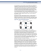
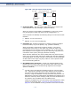
Table Of Contents
- About This Guide
- Contents
- Figures
- Tables
- Getting Started
- Web Configuration
- Using the Web Interface
- Basic Management Tasks
- Displaying System Information
- Displaying Hardware/Software Versions
- Configuring Support for Jumbo Frames
- Displaying Bridge Extension Capabilities
- Managing System Files
- Setting the System Clock
- Configuring the Console Port
- Configuring Telnet Settings
- Displaying CPU Utilization
- Displaying Memory Utilization
- Resetting the System
- Interface Configuration
- VLAN Configuration
- Address Table Settings
- Spanning Tree Algorithm
- Congestion Control
- Class of Service
- Quality of Service
- VoIP Traffic Configuration
- Security Measures
- AAA Authentication, Authorization and Accounting
- Configuring User Accounts
- Web Authentication
- Network Access (MAC Address Authentication)
- Configuring HTTPS
- Configuring the Secure Shell
- Access Control Lists
- Setting a Time Range
- Showing TCAM Utilization
- Setting the ACL Name and Type
- Configuring a Standard IPv4 ACL
- Configuring an Extended IPv4 ACL
- Configuring a Standard IPv6 ACL
- Configuring an Extended IPv6 ACL
- Configuring a MAC ACL
- Configuring an ARP ACL
- Binding a Port to an Access Control List
- Configuring ACL Mirroring
- Showing ACL Hardware Counters
- ARP Inspection
- Filtering IP Addresses for Management Access
- Configuring Port Security
- Configuring 802.1X Port Authentication
- DoS Protection
- IPv4 Source Guard
- IPv6 Source Guard
- DHCP Snooping
- Basic Administration Protocols
- Configuring Event Logging
- Link Layer Discovery Protocol
- Power over Ethernet
- Simple Network Management Protocol
- Configuring Global Settings for SNMP
- Setting the Local Engine ID
- Specifying a Remote Engine ID
- Setting SNMPv3 Views
- Configuring SNMPv3 Groups
- Setting Community Access Strings
- Configuring Local SNMPv3 Users
- Configuring Remote SNMPv3 Users
- Specifying Trap Managers
- Creating SNMP Notification Logs
- Showing SNMP Statistics
- Remote Monitoring
- Switch Clustering
- Ethernet Ring Protection Switching
- Connectivity Fault Management
- Configuring Global Settings for CFM
- Configuring Interfaces for CFM
- Configuring CFM Maintenance Domains
- Configuring CFM Maintenance Associations
- Configuring Maintenance End Points
- Configuring Remote Maintenance End Points
- Transmitting Link Trace Messages
- Transmitting Loop Back Messages
- Transmitting Delay-Measure Requests
- Displaying Local MEPs
- Displaying Details for Local MEPs
- Displaying Local MIPs
- Displaying Remote MEPs
- Displaying Details for Remote MEPs
- Displaying the Link Trace Cache
- Displaying Fault Notification Settings
- Displaying Continuity Check Errors
- OAM Configuration
- Multicast Filtering
- Overview
- Layer 2 IGMP (Snooping and Query for IPv4)
- Configuring IGMP Snooping and Query Parameters
- Specifying Static Interfaces for a Multicast Router
- Assigning Interfaces to Multicast Services
- Setting IGMP Snooping Status per Interface
- Filtering IGMP Query Packets and Multicast Data
- Displaying Multicast Groups Discovered by IGMP Snooping
- Displaying IGMP Snooping Statistics
- Filtering and Throttling IGMP Groups
- MLD Snooping (Snooping and Query for IPv6)
- Multicast VLAN Registration for IPv4
- Multicast VLAN Registration for IPv6
- IP Configuration
- IP Services
- General IP Routing
- Command Line Interface
- Using the Command Line Interface
- General Commands
- System Management Commands
- SNMP Commands
- Remote Monitoring Commands
- Authentication Commands
- User Accounts and Privilege Levels
- Authentication Sequence
- RADIUS Client
- TACACS+ Client
- AAA
- Web Server
- Telnet Server
- Secure Shell
- 802.1X Port Authentication
- Management IP Filter
- PPPoE Intermediate Agent
- pppoe intermediate-agent
- pppoe intermediate-agent format-type
- pppoe intermediate-agent port-enable
- pppoe intermediate-agent port-format-type
- pppoe intermediate-agent trust
- pppoe intermediate-agent vendor-tag strip
- clear pppoe intermediate-agent statistics
- show pppoe intermediate-agent info
- show pppoe intermediate-agent statistics
- General Security Measures
- Port Security
- Network Access (MAC Address Authentication)
- network-access aging
- network-access mac-filter
- mac-authentication reauth-time
- network-access dynamic-qos
- network-access dynamic-vlan
- network-access guest-vlan
- network-access link-detection
- network-access link-detection link-down
- network-access link-detection link-up
- network-access link-detection link-up-down
- network-access max-mac-count
- network-access mode mac-authentication
- network-access port-mac-filter
- mac-authentication intrusion-action
- mac-authentication max-mac-count
- clear network-access
- show network-access
- show network-access mac-address-table
- show network-access mac-filter
- Web Authentication
- DHCPv4 Snooping
- ip dhcp snooping
- ip dhcp snooping information option
- ip dhcp snooping information policy
- ip dhcp snooping limit rate
- ip dhcp snooping verify mac-address
- ip dhcp snooping vlan
- ip dhcp snooping information option circuit-id
- ip dhcp snooping trust
- clear ip dhcp snooping binding
- clear ip dhcp snooping database flash
- ip dhcp snooping database flash
- show ip dhcp snooping
- show ip dhcp snooping binding
- DHCPv6 Snooping
- ipv6 dhcp snooping
- ipv6 dhcp snooping option remote-id
- ipv6 dhcp snooping option remote-id policy
- ipv6 dhcp snooping vlan
- ipv6 dhcp snooping max-binding
- ipv6 dhcp snooping trust
- clear ipv6 dhcp snooping binding
- clear ipv6 dhcp snooping database flash
- show ipv6 dhcp snooping
- show ipv6 dhcp snooping binding
- show ipv6 dhcp snooping statistics
- IPv4 Source Guard
- IPv6 Source Guard
- ARP Inspection
- ip arp inspection
- ip arp inspection filter
- ip arp inspection log-buffer logs
- ip arp inspection validate
- ip arp inspection vlan
- ip arp inspection limit
- ip arp inspection trust
- show ip arp inspection configuration
- show ip arp inspection interface
- show ip arp inspection log
- show ip arp inspection statistics
- show ip arp inspection vlan
- Denial of Service Protection
- Port-based Traffic Segmentation
- Access Control Lists
- Interface Commands
- Link Aggregation Commands
- Power over Ethernet Commands
- Port Mirroring Commands
- Congestion Control Commands
- Rate Limit Commands
- Storm Control Commands
- Automatic Traffic Control Commands
- Threshold Commands
- SNMP Trap Commands
- snmp-server enable port-traps atc broadcast- alarm-clear
- snmp-server enable port-traps atc broadcast- alarm-fire
- snmp-server enable port-traps atc broadcast- control-apply
- snmp-server enable port-traps atc broadcast- control-release
- snmp-server enable port-traps atc multicast-alarm- clear
- snmp-server enable port-traps atc multicast-alarm- fire
- snmp-server enable port-traps atc multicast- control-apply
- snmp-server enable port-traps atc multicast- control-release
- ATC Display Commands
- Loopback Detection Commands
- UniDirectional Link Detection Commands
- Address Table Commands
- Spanning Tree Commands
- spanning-tree
- spanning-tree cisco-prestandard
- spanning-tree forward-time
- spanning-tree hello-time
- spanning-tree max-age
- spanning-tree mode
- spanning-tree pathcost method
- spanning-tree priority
- spanning-tree mst configuration
- spanning-tree system-bpdu- flooding
- spanning-tree transmission-limit
- max-hops
- mst priority
- mst vlan
- name
- revision
- spanning-tree bpdu-filter
- spanning-tree bpdu-guard
- spanning-tree cost
- spanning-tree edge-port
- spanning-tree link-type
- spanning-tree loopback-detection
- spanning-tree loopback-detection action
- spanning-tree loopback-detection release-mode
- spanning-tree loopback-detection trap
- spanning-tree mst cost
- spanning-tree mst port-priority
- spanning-tree port-bpdu-flooding
- spanning-tree port-priority
- spanning-tree root-guard
- spanning-tree spanning-disabled
- spanning-tree tc-prop-stop
- spanning-tree loopback-detection release
- spanning-tree protocol-migration
- show spanning-tree
- show spanning-tree mst configuration
- ERPS Commands
- VLAN Commands
- GVRP and Bridge Extension Commands
- Editing VLAN Groups
- Configuring VLAN Interfaces
- Displaying VLAN Information
- Configuring IEEE 802.1Q Tunneling
- Configuring L2CP Tunneling
- Configuring VLAN Translation
- Configuring Protocol-based VLANs
- Configuring IP Subnet VLANs
- Configuring MAC Based VLANs
- Configuring Voice VLANs
- Class of Service Commands
- Quality of Service Commands
- Multicast Filtering Commands
- IGMP Snooping
- ip igmp snooping
- ip igmp snooping priority
- ip igmp snooping proxy-reporting
- ip igmp snooping querier
- ip igmp snooping router-alert-option- check
- ip igmp snooping router-port- expire-time
- ip igmp snooping tcn-flood
- ip igmp snooping tcn-query-solicit
- ip igmp snooping unregistered- data-flood
- ip igmp snooping unsolicited-report- interval
- ip igmp snooping version
- ip igmp snooping version-exclusive
- ip igmp snooping vlan general-query- suppression
- ip igmp snooping vlan immediate-leave
- ip igmp snooping vlan last-memb- query-count
- ip igmp snooping vlan last-memb- query-intvl
- ip igmp snooping vlan mrd
- ip igmp snooping vlan proxy-address
- ip igmp snooping vlan query-interval
- ip igmp snooping vlan query-resp-intvl
- ip igmp snooping vlan static
- clear ip igmp snooping groups dynamic
- clear ip igmp snooping statistics
- show ip igmp snooping
- show ip igmp snooping group
- show ip igmp snooping mrouter
- show ip igmp snooping statistics
- Static Multicast Routing
- IGMP Filtering and Throttling
- ip igmp filter (Global Configuration)
- ip igmp profile
- permit, deny
- range
- ip igmp authentication
- ip igmp filter (Interface Configuration)
- ip igmp max-groups
- ip igmp max-groups action
- ip igmp query-drop
- ip multicast-data-drop
- show ip igmp authentication
- show ip igmp filter
- show ip igmp profile
- show ip igmp query-drop
- show ip igmp throttle interface
- show ip multicast-data-drop
- MLD Snooping
- ipv6 mld snooping
- ipv6 mld snooping querier
- ipv6 mld snooping query-interval
- ipv6 mld snooping query-max- response-time
- ipv6 mld snooping robustness
- ipv6 mld snooping router-port-expire- time
- ipv6 mld snooping unknown-multicast mode
- ipv6 mld snooping version
- ipv6 mld snooping vlan immediate- leave
- ipv6 mld snooping vlan mrouter
- ipv6 mld snooping vlan static
- clear ipv6 mld snooping groups dynamic
- clear ipv6 mld snooping statistics
- show ipv6 mld snooping
- show ipv6 mld snooping group
- show ipv6 mld snooping group source-list
- show ipv6 mld snooping mrouter
- MLD Filtering and Throttling
- MVR for IPv4
- mvr
- mvr associated-profile
- mvr domain
- mvr priority
- mvr profile
- mvr proxy- query-interval
- mvr proxy-switching
- mvr robustness-value
- mvr source-port-mode dynamic
- mvr upstream-source-ip
- mvr vlan
- mvr immediate-leave
- mvr type
- mvr vlan group
- clear mrv groups dynamic
- clear mrv statistics
- show mvr
- show mvr associated-profile
- show mvr interface
- show mvr members
- show mvr profile
- show mvr statistics
- MVR for IPv6
- mvr6 associated-profile
- mvr6 domain
- mvr6 priority
- mvr6 profile
- mvr6 proxy-query-interval
- mvr6 proxy-switching
- mvr6 robustness-value
- mvr6 source-port-mode dynamic
- mvr6 upstream-source-ip
- mvr6 vlan
- mvr6 immediate-leave
- mvr6 type
- mvr6 vlan group
- clear mvr6 groups dynamic
- clear mvr6 statistics
- show mvr6
- show mvr6 associated-profile
- show mvr6 interface
- show mvr6 members
- show mvr6 profile
- show mvr6 statistics
- IGMP Snooping
- LLDP Commands
- lldp
- lldp holdtime- multiplier
- lldp med-fast-start-count
- lldp notification-interval
- lldp refresh-interval
- lldp reinit-delay
- lldp tx-delay
- lldp admin-status
- lldp basic-tlv management-ip- address
- lldp basic-tlv port-description
- lldp basic-tlv system-capabilities
- lldp basic-tlv system-description
- lldp basic-tlv system-name
- lldp dot1-tlv proto-ident
- lldp dot1-tlv proto-vid
- lldp dot1-tlv pvid
- lldp dot1-tlv vlan-name
- lldp dot3-tlv link-agg
- lldp dot3-tlv mac-phy
- lldp dot3-tlv max-frame
- lldp dot3-tlv poe
- lldp med-location civic-addr
- lldp med-notification
- lldp med-tlv ext-poe
- lldp med-tlv inventory
- lldp med-tlv location
- lldp med-tlv med-cap
- lldp med-tlv network-policy
- lldp notification
- show lldp config
- show lldp info local-device
- show lldp info remote-device
- show lldp info statistics
- CFM Commands
- Defining CFM Structures
- ethernet cfm ais level
- ethernet cfm ais ma
- ethernet cfm ais period
- ethernet cfm ais suppress alarm
- ethernet cfm domain
- ethernet cfm enable
- ma index name
- ma index name-format
- ethernet cfm mep
- ethernet cfm port-enable
- clear ethernet cfm ais mpid
- show ethernet cfm configuration
- show ethernet cfm md
- show ethernet cfm ma
- show ethernet cfm maintenance-points local
- show ethernet cfm maintenance-points local detail mep
- show ethernet cfm maintenance-points remote detail
- Continuity Check Operations
- Cross Check Operations
- Link Trace Operations
- Loopback Operations
- Fault Generator Operations
- Delay Measure Operations
- Defining CFM Structures
- OAM Commands
- efm oam
- efm oam critical-link-event
- efm oam link-monitor frame
- efm oam link-monitor frame threshold
- efm oam link-monitor frame window
- efm oam mode
- clear efm oam counters
- clear efm oam event-log
- efm oam remote-loopback
- efm oam remote-loopback test
- show efm oam counters interface
- show efm oam event-log interface
- show efm oam remote-loopback interface
- show efm oam status interface
- show efm oam status remote interface
- Domain Name Service Commands
- DHCP Commands
- IP Interface Commands
- IPv4 Interface
- IPv6 Interface
- ND Snooping
- ipv6 nd snooping
- ipv6 nd snooping auto-detect
- ipv6 nd snooping auto-detect retransmit count
- ipv6 nd snooping auto-detect retransmit interval
- ipv6 nd snooping prefix timeout
- ipv6 nd snooping max-binding
- ipv6 nd snooping trust
- clear ipv6 nd snooping binding
- clear ipv6 nd snooping prefix
- show ipv6 nd snooping
- show ipv6 nd snooping binding
- show ipv6 nd snooping prefix
- IP Routing Commands
- Appendices
- Glossary
- Command List
- Index

C
HAPTER
14
| Basic Administration Protocols
Ethernet Ring Protection Switching
– 503 –
When ring nodes running G.8032v1 and G.8032v2 co-exist on a ring,
the ring ID of each node is configured as “1”.
In version 1, the MAC address 01-19-A7-00-00-01 is used for the node
identifier. The R-APS Def MAC parameter has no effect.
◆ MEG Level – The maintenance entity group (MEG) level which provides
a communication channel for ring automatic protection switching
(R-APS) information. (Range: 0-7)
This parameter is used to ensure that received R-APS PDUs are directed
for this ring. A unique level should be configured for each local ring if
there are many R-APS PDUs passing through this switch.
◆ Control VLAN – A dedicated VLAN used for sending and receiving
E-APS protocol messages. (Range: 1-4094)
Configure one control VLAN for each ERPS ring. First create the VLAN to
be used as the control VLAN (see "Configuring VLAN Groups" on
page 202), add the ring ports for the east and west interface as tagged
members to this VLAN (see "Adding Static Members to VLANs" on
page 205), and then use this parameter to add it to the ring.
The following restrictions are recommended to avoid creating a loop in
the network or other problems which may occur under some situations:
■
The Control VLAN must not be configured as a Layer 3 interface
(with an IP address), a dynamic VLAN (with GVRP enabled), nor as
a private VLAN.
■
In addition, only ring ports may be added to the Control VLAN. No
other ports can be members of this VLAN.
■
Also, the ring ports of the Control VLAN must be tagged.
Once the ring has been activated, the configuration of the control VLAN
cannot be modified. Use the Admin Status parameter to stop the ERPS
ring before making any configuration changes to the control VLAN.
◆ Node State – Refer to the parameters for the Show page.
◆ Node Type – Shows ERPS node type as one of the following:
■
None – Node is neither Ring Protection Link (RPL) owner nor
neighbor. (This is the default setting.)
■
RPL Owner – Specifies a ring node to be the RPL owner.
■
Only one RPL owner can be configured on a ring. The owner
blocks traffic on the RPL during Idle state, and unblocks it during
Protection state (that is, when a signal fault is detected on the
ring or the protection state is enabled with the Forced Switch or
Manual Switch commands on the Configure Operation page).
■
The east and west connections to the ring must be specified for
all ring nodes. When this switch is configured as the RPL owner,
the west ring port is automatically set as being connected to the
RPL.