
ECS4110-28T_Installation Guide-R03
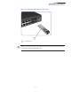
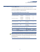

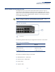
Table Of Contents
- How to Use This Guide
- Contents
- Figures
- Tables
- Switch Description
- Installation Overview
- Switch Chassis
- Power and Grounding
- Port Connections
- Switch Management
- Troubleshooting
- Index

Chapter 6
| Switch Management
Understanding the System Status LEDs
– 39 –
Understanding the System Status LEDs
The switch includes a display panel of key system LED indicators. The LEDs, which
are located on the front panel, are shown below and described in the following
table.
Figure 20: System Status LEDs
(
System Status LEDs
Table 9: System Status LEDs
LED Condition Status
PWR On Green Internal power operating normally.
Off No AC power is connected or the internal power supply
has failed.
DIAG
(Diagnostic)
On Green The system diagnostic test has completed successfully.
On Amber System diagnostic in progress.
Blinking Amber The system self-diagnostic test has detected a fault.
Blinking Amber and
Green
The switch system is booting up.
1
1