
ECS4110-28T_Installation Guide-R03
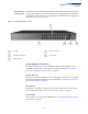
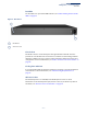
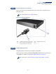
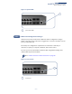
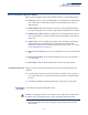
Table Of Contents
- How to Use This Guide
- Contents
- Figures
- Tables
- Switch Description
- Installation Overview
- Switch Chassis
- Power and Grounding
- Port Connections
- Switch Management
- Troubleshooting
- Index

Chapter 1
| Switch Description
Overview
– 11 –
Key Hardware
Components
The switch consist of serveral key hardware components. This manual describes
each specific component, or related components, together with their installation
requirements and procedures in each chapter. To understand each component in
detail, refer to the relevant section.
Figure 1: Front Panel ECS4110-28T
10/100/1000BASE-T RJ-45 Ports
The switch contains 24 10/100/1000BASE-T RJ-45 ports that support 10/100/
1000BASE-T copper links to other devices. For more information, see “How to
Connect to Twisted-Pair Copper Ports” on page 32.
Gigabit SFP Slots
The switch contains four Small Form Factor Pluggable (SFP) transceiver slots that
operate up to Gigabit full duplex. For more information, see “How to Connect to
SFP Fiber Optic Ports” on page 35.
Reset Button
Pressing the reset button on the rear panel causes the switch to execute a hard
reset. For more information, see “How to Reset the Switch” on page 42.
System LEDs
For information on system status LED indicators, see “Understanding the System
Status LEDs” on page 39.
Port LEDs RJ-45 Console Port
1000BASE-T RJ-45 Ports System LEDs
Gigabit SFP Slots
4
5
1
2
3
1
4
2
5
3