
ECS4100 Series Web Management Guide-R07
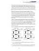
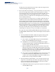
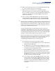
Table Of Contents
- How to Use This Guide
- Contents
- Figures
- Tables
- Getting Started
- Web Configuration
- Using the Web Interface
- Basic Management Tasks
- Displaying System Information
- Displaying Hardware/Software Versions
- Configuring Support for Jumbo Frames
- Displaying Bridge Extension Capabilities
- Managing System Files
- Setting the System Clock
- Configuring the Console Port
- Configuring Telnet Settings
- Displaying CPU Utilization
- Configuring CPU Guard
- Displaying Memory Utilization
- Resetting the System
- Using Cloud Management
- Interface Configuration
- VLAN Configuration
- Address Table Settings
- Spanning Tree Algorithm
- Congestion Control
- Class of Service
- Quality of Service
- VoIP Traffic Configuration
- Security Measures
- AAA (Authentication, Authorization and Accounting)
- Configuring User Accounts
- Web Authentication
- Network Access (MAC Address Authentication)
- Configuring HTTPS
- Configuring the Secure Shell
- Access Control Lists
- Filtering IP Addresses for Management Access
- Configuring Port Security
- Configuring 802.1X Port Authentication
- DoS Protection
- DHCP Snooping
- DHCPv6 Snooping
- IPv4 Source Guard
- IPv6 Source Guard
- ARP Inspection
- Application Filter
- Basic Administration Protocols
- Configuring Event Logging
- Link Layer Discovery Protocol
- Power over Ethernet
- Simple Network Management Protocol
- Configuring Global Settings for SNMP
- Setting Community Access Strings
- Setting the Local Engine ID
- Specifying a Remote Engine ID
- Setting SNMPv3 Views
- Configuring SNMPv3 Groups
- Configuring Local SNMPv3 Users
- Configuring Remote SNMPv3 Users
- Specifying Trap Managers
- Creating SNMP Notification Logs
- Showing SNMP Statistics
- Remote Monitoring
- Switch Clustering
- Setting a Time Range
- Ethernet Ring Protection Switching
- Connectivity Fault Management
- Configuring Global Settings for CFM
- Configuring Interfaces for CFM
- Configuring CFM Maintenance Domains
- Configuring CFM Maintenance Associations
- Configuring Maintenance End Points
- Configuring Remote Maintenance End Points
- Transmitting Link Trace Messages
- Transmitting Loop Back Messages
- Transmitting Delay-Measure Requests
- Displaying Local MEPs
- Displaying Details for Local MEPs
- Displaying Local MIPs
- Displaying Remote MEPs
- Displaying Details for Remote MEPs
- Displaying the Link Trace Cache
- Displaying Fault Notification Settings
- Displaying Continuity Check Errors
- OAM Configuration
- UDLD Configuration
- LBD Configuration
- Smart Pair Configuration
- Multicast Filtering
- Overview
- Layer 2 IGMP (Snooping and Query for IPv4)
- Configuring IGMP Snooping and Query Parameters
- Specifying Static Interfaces for a Multicast Router
- Assigning Interfaces to Multicast Services
- Setting IGMP Snooping Status per Interface
- Filtering IGMP Packets on an Interface
- Displaying Multicast Groups Discovered by IGMP Snooping
- Displaying IGMP Snooping Statistics
- Filtering and Throttling IGMP Groups
- MLD Snooping (Snooping and Query for IPv6)
- Configuring MLD Snooping and Query Parameters
- Setting Immediate Leave Status for MLD Snooping per Interface
- Specifying Static Interfaces for an IPv6 Multicast Router
- Assigning Interfaces to IPv6 Multicast Services
- Filtering MLD Query Packets on an Interface
- Showing MLD Snooping Groups and Source List
- Displaying MLD Snooping Statistics
- Filtering and Throttling MLD Groups
- Multicast VLAN Registration for IPv4
- Multicast VLAN Registration for IPv6
- IP Tools
- IP Configuration
- General IP Routing
- Unicast Routing
- Overview
- Configuring the Routing Information Protocol
- Configuring General Protocol Settings
- Clearing Entries from the Routing Table
- Specifying Network Interfaces
- Specifying Passive Interfaces
- Specifying Static Neighbors
- Configuring Route Redistribution
- Specifying an Administrative Distance
- Configuring Network Interfaces for RIP
- Displaying RIP Interface Settings
- Displaying Peer Router Information
- Resetting RIP Statistics
- IP Services
- Appendices

Chapter 13
| Basic Administration Protocols
Ethernet Ring Protection Switching
– 471 –
formed by the ring links of ERP2 and the ring link between the interconnection
nodes that is controlled by ERP1. ERP2 is a sub-ring. Ring node A is the RPL owner
node for ERP1, and ring node E is the RPL owner node for ERP2. These ring nodes (A
and E) are responsible for blocking the traffic channel on the RPL for ERP1 and ERP2
respectively. There is no restriction on which ring link on an ring may be set as the
RPL. For example the RPL of ERP1 could be set as the link between ring node C and
D.
Ring nodes C and D, that are common to both ERP1 and ERP2, are called
interconnection nodes. The ring link between the interconnection nodes are
controlled and protected by the ring it belongs to. In the example for the Normal
Condition, the ring link between ring nodes C and D is part of ERP1, and, as such,
are controlled and protected by ERP1. Ethernet characteristic information traffic
corresponding to the traffic channel may be transferred over a common Ethernet
connection for ERP1 and ERP2 through the interconnection nodes C and D.
Interconnection nodes C and D have separate ERP Control Processes for each
Ethernet Ring.
Figure 305 on page 471 (Signal Fail Condition) illustrates a situation where
protection switching has occurred due to an SF condition on the ring link between
interconnection nodes C and D. The failure of this ring link triggers protection only
on the ring to which it belongs, in this case ERP1. The traffic and R-APS channels are
blocked bi-directionally on the ports where the failure is detected and bi-
directionally unblocked at the RPL connection point on ERP1. The traffic channels
remain bi-directionally blocked at the RPL connection point on ERP2. This prevents
the formation of a loop.
Figure 305:
Ring Interconnection Architecture (Multi-ring/Ladder Network)
Configuration Guidelines for ERPS
1. Create an ERPS ring (Configure Domain – Add): The ring name is used as an
index in the G.8032 database.
2. Configure the east and west interfaces (Configure Domain – Configure Details):
Each node on the ring connects to it through two ring ports. Configure one
ring node Aring node B
ring node C ring node D
ring node F ring node E
ERP1
ERP2
RPL
RPL
RPL Owner
Node
for ERP1
RPL Owner
Node
for ERP2
ring link
(ERP1)
ring no de Aring node B
ring node C ring no de D
ring node F ring no de E
ERP1
ERP2
RPL
RPL
RPL Owner
Node
for ERP1
RPL Owner
Node
for ERP2
ring link
(ERP1)
FAILURE
Normal Condition Signal Fail Condition