
ECS4100 Series Web Management Guide-R07
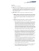
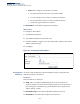
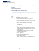
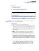
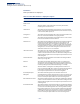
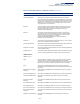
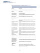
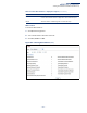
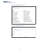
Table Of Contents
- How to Use This Guide
- Contents
- Figures
- Tables
- Getting Started
- Web Configuration
- Using the Web Interface
- Basic Management Tasks
- Displaying System Information
- Displaying Hardware/Software Versions
- Configuring Support for Jumbo Frames
- Displaying Bridge Extension Capabilities
- Managing System Files
- Setting the System Clock
- Configuring the Console Port
- Configuring Telnet Settings
- Displaying CPU Utilization
- Configuring CPU Guard
- Displaying Memory Utilization
- Resetting the System
- Using Cloud Management
- Interface Configuration
- VLAN Configuration
- Address Table Settings
- Spanning Tree Algorithm
- Congestion Control
- Class of Service
- Quality of Service
- VoIP Traffic Configuration
- Security Measures
- AAA (Authentication, Authorization and Accounting)
- Configuring User Accounts
- Web Authentication
- Network Access (MAC Address Authentication)
- Configuring HTTPS
- Configuring the Secure Shell
- Access Control Lists
- Filtering IP Addresses for Management Access
- Configuring Port Security
- Configuring 802.1X Port Authentication
- DoS Protection
- DHCP Snooping
- DHCPv6 Snooping
- IPv4 Source Guard
- IPv6 Source Guard
- ARP Inspection
- Application Filter
- Basic Administration Protocols
- Configuring Event Logging
- Link Layer Discovery Protocol
- Power over Ethernet
- Simple Network Management Protocol
- Configuring Global Settings for SNMP
- Setting Community Access Strings
- Setting the Local Engine ID
- Specifying a Remote Engine ID
- Setting SNMPv3 Views
- Configuring SNMPv3 Groups
- Configuring Local SNMPv3 Users
- Configuring Remote SNMPv3 Users
- Specifying Trap Managers
- Creating SNMP Notification Logs
- Showing SNMP Statistics
- Remote Monitoring
- Switch Clustering
- Setting a Time Range
- Ethernet Ring Protection Switching
- Connectivity Fault Management
- Configuring Global Settings for CFM
- Configuring Interfaces for CFM
- Configuring CFM Maintenance Domains
- Configuring CFM Maintenance Associations
- Configuring Maintenance End Points
- Configuring Remote Maintenance End Points
- Transmitting Link Trace Messages
- Transmitting Loop Back Messages
- Transmitting Delay-Measure Requests
- Displaying Local MEPs
- Displaying Details for Local MEPs
- Displaying Local MIPs
- Displaying Remote MEPs
- Displaying Details for Remote MEPs
- Displaying the Link Trace Cache
- Displaying Fault Notification Settings
- Displaying Continuity Check Errors
- OAM Configuration
- UDLD Configuration
- LBD Configuration
- Smart Pair Configuration
- Multicast Filtering
- Overview
- Layer 2 IGMP (Snooping and Query for IPv4)
- Configuring IGMP Snooping and Query Parameters
- Specifying Static Interfaces for a Multicast Router
- Assigning Interfaces to Multicast Services
- Setting IGMP Snooping Status per Interface
- Filtering IGMP Packets on an Interface
- Displaying Multicast Groups Discovered by IGMP Snooping
- Displaying IGMP Snooping Statistics
- Filtering and Throttling IGMP Groups
- MLD Snooping (Snooping and Query for IPv6)
- Configuring MLD Snooping and Query Parameters
- Setting Immediate Leave Status for MLD Snooping per Interface
- Specifying Static Interfaces for an IPv6 Multicast Router
- Assigning Interfaces to IPv6 Multicast Services
- Filtering MLD Query Packets on an Interface
- Showing MLD Snooping Groups and Source List
- Displaying MLD Snooping Statistics
- Filtering and Throttling MLD Groups
- Multicast VLAN Registration for IPv4
- Multicast VLAN Registration for IPv6
- IP Tools
- IP Configuration
- General IP Routing
- Unicast Routing
- Overview
- Configuring the Routing Information Protocol
- Configuring General Protocol Settings
- Clearing Entries from the Routing Table
- Specifying Network Interfaces
- Specifying Passive Interfaces
- Specifying Static Neighbors
- Configuring Route Redistribution
- Specifying an Administrative Distance
- Configuring Network Interfaces for RIP
- Displaying RIP Interface Settings
- Displaying Peer Router Information
- Resetting RIP Statistics
- IP Services
- Appendices

Chapter 16
| IP Configuration
Setting the Switch’s IP Address (IP Version 6)
– 661 –
Parameters
These parameters are displayed:
◆ VLAN – ID of a configured VLAN which is to be used for management access, or
for creating an interface to multiple subnets. By default, all ports on the switch
are members of VLAN 1. However, the management station can be attached to
a port belonging to any VLAN, as long as that VLAN has been assigned an IP
address. (Range: 1-4094)
◆ Address Type – Defines the address type configured for this interface.
■
Global – Configures an IPv6 global unicast address with a full IPv6 address
including the network prefix and host address bits, followed by a forward
slash, and a decimal value indicating how many contiguous bits (from the
left) of the address comprise the prefix (i.e., the network portion of the
address).
■
EUI-64 (Extended Universal Identifier) – Configures an IPv6 address for an
interface using an EUI-64 interface ID in the low order 64 bits.
■
When using EUI-64 format for the low-order 64 bits in the host portion
of the address, the value entered in the IPv6 Address field includes the
network portion of the address, and the prefix length indicates how
many contiguous bits (starting at the left) of the address comprise the
prefix (i.e., the network portion of the address). Note that the value
specified in the IPv6 Address field may include some of the high-order
host bits if the specified prefix length is less than 64 bits. If the specified
prefix length exceeds 64 bits, then the bits used in the network portion
of the address will take precedence over the interface identifier.
■
IPv6 addresses are 16 bytes long, of which the bottom 8 bytes typically
form a unique host identifier based on the device’s MAC address. The
EUI-64 specification is designed for devices that use an extended 8-
byte MAC address. For devices that still use a 6-byte MAC address (also
known as EUI-48 format), it must be converted into EUI-64 format by
inverting the universal/local bit in the address and inserting the
hexadecimal number FFFE between the upper and lower three bytes of
the MAC address.
For example, if a device had an EUI-48 address of 28-9F-18-1C-82-35,
the global/local bit must first be inverted to meet EUI-64 requirements
(i.e., 1 for globally defined addresses and 0 for locally defined
addresses), changing 28 to 2A. Then the two bytes FFFE are inserted
between the OUI (i.e., organizationally unique identifier, or company
identifier) and the rest of the address, resulting in a modified EUI-64
interface identifier of 2A-9F-18-FF-FE-1C-82-35.
■
This host addressing method allows the same interface identifier to be
used on multiple IP interfaces of a single device, as long as those
interfaces are attached to different subnets.