
ECS4100 Series Web Management Guide-R07
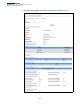
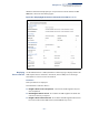

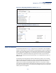
Table Of Contents
- How to Use This Guide
- Contents
- Figures
- Tables
- Getting Started
- Web Configuration
- Using the Web Interface
- Basic Management Tasks
- Displaying System Information
- Displaying Hardware/Software Versions
- Configuring Support for Jumbo Frames
- Displaying Bridge Extension Capabilities
- Managing System Files
- Setting the System Clock
- Configuring the Console Port
- Configuring Telnet Settings
- Displaying CPU Utilization
- Configuring CPU Guard
- Displaying Memory Utilization
- Resetting the System
- Using Cloud Management
- Interface Configuration
- VLAN Configuration
- Address Table Settings
- Spanning Tree Algorithm
- Congestion Control
- Class of Service
- Quality of Service
- VoIP Traffic Configuration
- Security Measures
- AAA (Authentication, Authorization and Accounting)
- Configuring User Accounts
- Web Authentication
- Network Access (MAC Address Authentication)
- Configuring HTTPS
- Configuring the Secure Shell
- Access Control Lists
- Filtering IP Addresses for Management Access
- Configuring Port Security
- Configuring 802.1X Port Authentication
- DoS Protection
- DHCP Snooping
- DHCPv6 Snooping
- IPv4 Source Guard
- IPv6 Source Guard
- ARP Inspection
- Application Filter
- Basic Administration Protocols
- Configuring Event Logging
- Link Layer Discovery Protocol
- Power over Ethernet
- Simple Network Management Protocol
- Configuring Global Settings for SNMP
- Setting Community Access Strings
- Setting the Local Engine ID
- Specifying a Remote Engine ID
- Setting SNMPv3 Views
- Configuring SNMPv3 Groups
- Configuring Local SNMPv3 Users
- Configuring Remote SNMPv3 Users
- Specifying Trap Managers
- Creating SNMP Notification Logs
- Showing SNMP Statistics
- Remote Monitoring
- Switch Clustering
- Setting a Time Range
- Ethernet Ring Protection Switching
- Connectivity Fault Management
- Configuring Global Settings for CFM
- Configuring Interfaces for CFM
- Configuring CFM Maintenance Domains
- Configuring CFM Maintenance Associations
- Configuring Maintenance End Points
- Configuring Remote Maintenance End Points
- Transmitting Link Trace Messages
- Transmitting Loop Back Messages
- Transmitting Delay-Measure Requests
- Displaying Local MEPs
- Displaying Details for Local MEPs
- Displaying Local MIPs
- Displaying Remote MEPs
- Displaying Details for Remote MEPs
- Displaying the Link Trace Cache
- Displaying Fault Notification Settings
- Displaying Continuity Check Errors
- OAM Configuration
- UDLD Configuration
- LBD Configuration
- Smart Pair Configuration
- Multicast Filtering
- Overview
- Layer 2 IGMP (Snooping and Query for IPv4)
- Configuring IGMP Snooping and Query Parameters
- Specifying Static Interfaces for a Multicast Router
- Assigning Interfaces to Multicast Services
- Setting IGMP Snooping Status per Interface
- Filtering IGMP Packets on an Interface
- Displaying Multicast Groups Discovered by IGMP Snooping
- Displaying IGMP Snooping Statistics
- Filtering and Throttling IGMP Groups
- MLD Snooping (Snooping and Query for IPv6)
- Configuring MLD Snooping and Query Parameters
- Setting Immediate Leave Status for MLD Snooping per Interface
- Specifying Static Interfaces for an IPv6 Multicast Router
- Assigning Interfaces to IPv6 Multicast Services
- Filtering MLD Query Packets on an Interface
- Showing MLD Snooping Groups and Source List
- Displaying MLD Snooping Statistics
- Filtering and Throttling MLD Groups
- Multicast VLAN Registration for IPv4
- Multicast VLAN Registration for IPv6
- IP Tools
- IP Configuration
- General IP Routing
- Unicast Routing
- Overview
- Configuring the Routing Information Protocol
- Configuring General Protocol Settings
- Clearing Entries from the Routing Table
- Specifying Network Interfaces
- Specifying Passive Interfaces
- Specifying Static Neighbors
- Configuring Route Redistribution
- Specifying an Administrative Distance
- Configuring Network Interfaces for RIP
- Displaying RIP Interface Settings
- Displaying Peer Router Information
- Resetting RIP Statistics
- IP Services
- Appendices

Chapter 13
| Basic Administration Protocols
Power over Ethernet
– 420 –
Ports can be set to one of three power priority levels, critical, high or low. To control
the power supply within the switch’s budget, ports set at critical to high priority
have power enabled in preference to those ports set at low priority. For example,
when a device connected to a port is set to critical priority, the switch supplies the
required power, if necessary by denying power to ports set for a lower priority
during bootup.
Setting the Switch’s
Overall PoE Power
Budget
Use the Administration > PoE > PSE (Configure Global) page to set the maximum
PoE power budget for the switch (power available to all RJ-45 ports). The maximum
power budget is fixed at the maximum available setting, which prevents overload
conditions at the power source. If the power demand from devices connected to
the switch exceeds the power budget, the switch uses port power priority settings
to limit the supplied power.
Parameters
These parameters are displayed:
◆ PoE Maximum Available Power – The power budget for the switch. If devices
connected to the switch require more power than the switch budget, the port
power priority settings are used to control the supplied power. Overall
allocated power cannot exceed this setting.
◆ PoE Maximum Allocation Power – Status of the PoE power service provided
to the switch ports.
◆ PoE Power Consumption – Sets a power budget for the switch.
■
(ECS4100-28P: 50000-190000 milliwatts; Default: 190000 mW
■
ECS4100-52P: 50000-370000 milliwatts; Default: 370000 mW
■
ECS4100-12PH: 50000-180000 milliwatts; Default: 180000 mW)
◆ Compatible Mode – Allows the switch to detect and provide power to
powered devices that were designed prior to the IEEE 802.3af PoE standard.
(Default: Disabled)
The switch automatically detects attached PoE devices by periodically
transmitting test voltages that over the Gigabit Ethernet copper-media ports.
When an IEEE 802.3af or 802.3at compatible device is plugged into one of these
ports, the powered device reflects the test voltage back to the switch, which
may then turn on the power to this device. When the compatibility mode is
enabled, this switch can detect IEEE 802.3af or 802.3at compliant devices and
the more recent 802.3af non-compliant devices that also reflect the test
voltages back to the switch. It cannot detect other legacy devices that do not
reflect back the test voltages.
For legacy devices to be supported by this switch, they must be able to accept
power over the data pairs connected to the RJ-45 ports