
ECS4100 Series Web Management Guide-R07
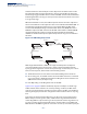
Table Of Contents
- How to Use This Guide
- Contents
- Figures
- Tables
- Getting Started
- Web Configuration
- Using the Web Interface
- Basic Management Tasks
- Displaying System Information
- Displaying Hardware/Software Versions
- Configuring Support for Jumbo Frames
- Displaying Bridge Extension Capabilities
- Managing System Files
- Setting the System Clock
- Configuring the Console Port
- Configuring Telnet Settings
- Displaying CPU Utilization
- Configuring CPU Guard
- Displaying Memory Utilization
- Resetting the System
- Using Cloud Management
- Interface Configuration
- VLAN Configuration
- Address Table Settings
- Spanning Tree Algorithm
- Congestion Control
- Class of Service
- Quality of Service
- VoIP Traffic Configuration
- Security Measures
- AAA (Authentication, Authorization and Accounting)
- Configuring User Accounts
- Web Authentication
- Network Access (MAC Address Authentication)
- Configuring HTTPS
- Configuring the Secure Shell
- Access Control Lists
- Filtering IP Addresses for Management Access
- Configuring Port Security
- Configuring 802.1X Port Authentication
- DoS Protection
- DHCP Snooping
- DHCPv6 Snooping
- IPv4 Source Guard
- IPv6 Source Guard
- ARP Inspection
- Application Filter
- Basic Administration Protocols
- Configuring Event Logging
- Link Layer Discovery Protocol
- Power over Ethernet
- Simple Network Management Protocol
- Configuring Global Settings for SNMP
- Setting Community Access Strings
- Setting the Local Engine ID
- Specifying a Remote Engine ID
- Setting SNMPv3 Views
- Configuring SNMPv3 Groups
- Configuring Local SNMPv3 Users
- Configuring Remote SNMPv3 Users
- Specifying Trap Managers
- Creating SNMP Notification Logs
- Showing SNMP Statistics
- Remote Monitoring
- Switch Clustering
- Setting a Time Range
- Ethernet Ring Protection Switching
- Connectivity Fault Management
- Configuring Global Settings for CFM
- Configuring Interfaces for CFM
- Configuring CFM Maintenance Domains
- Configuring CFM Maintenance Associations
- Configuring Maintenance End Points
- Configuring Remote Maintenance End Points
- Transmitting Link Trace Messages
- Transmitting Loop Back Messages
- Transmitting Delay-Measure Requests
- Displaying Local MEPs
- Displaying Details for Local MEPs
- Displaying Local MIPs
- Displaying Remote MEPs
- Displaying Details for Remote MEPs
- Displaying the Link Trace Cache
- Displaying Fault Notification Settings
- Displaying Continuity Check Errors
- OAM Configuration
- UDLD Configuration
- LBD Configuration
- Smart Pair Configuration
- Multicast Filtering
- Overview
- Layer 2 IGMP (Snooping and Query for IPv4)
- Configuring IGMP Snooping and Query Parameters
- Specifying Static Interfaces for a Multicast Router
- Assigning Interfaces to Multicast Services
- Setting IGMP Snooping Status per Interface
- Filtering IGMP Packets on an Interface
- Displaying Multicast Groups Discovered by IGMP Snooping
- Displaying IGMP Snooping Statistics
- Filtering and Throttling IGMP Groups
- MLD Snooping (Snooping and Query for IPv6)
- Configuring MLD Snooping and Query Parameters
- Setting Immediate Leave Status for MLD Snooping per Interface
- Specifying Static Interfaces for an IPv6 Multicast Router
- Assigning Interfaces to IPv6 Multicast Services
- Filtering MLD Query Packets on an Interface
- Showing MLD Snooping Groups and Source List
- Displaying MLD Snooping Statistics
- Filtering and Throttling MLD Groups
- Multicast VLAN Registration for IPv4
- Multicast VLAN Registration for IPv6
- IP Tools
- IP Configuration
- General IP Routing
- Unicast Routing
- Overview
- Configuring the Routing Information Protocol
- Configuring General Protocol Settings
- Clearing Entries from the Routing Table
- Specifying Network Interfaces
- Specifying Passive Interfaces
- Specifying Static Neighbors
- Configuring Route Redistribution
- Specifying an Administrative Distance
- Configuring Network Interfaces for RIP
- Displaying RIP Interface Settings
- Displaying Peer Router Information
- Resetting RIP Statistics
- IP Services
- Appendices

Chapter 13
| Basic Administration Protocols
Ethernet Ring Protection Switching
– 469 –
Ethernet Ring Protection Switching
Note:
Information in this section is based on ITU-T G.8032/Y.1344.
The ITU G.8032 recommendation specifies a protection switching mechanism and
protocol for Ethernet layer network rings. Ethernet rings can provide wide-area
multipoint connectivity more economically due to their reduced number of links.
The mechanisms and protocol defined in G.8032 achieve highly reliable and stable
protection; and never form loops, which would fatally affect network operation and
service availability.
The G.8032 recommendation, also referred to as Ethernet Ring Protection
Switching (ERPS), can be used to increase the availability and robustness of
Ethernet rings. An Ethernet ring built using ERPS can provide resilience at a lower
cost and than that provided by SONET or EAPS rings.
ERPS is more economical than EAPS in that only one physical link is required
between each node in the ring. However, since it can tolerate only one break in the
ring, it is not as robust as EAPS. ERPS supports up to 255 nodes in the ring structure.
ERPS requires a higher convergence time when more that 16 nodes are used, but
should always run under than 500 ms.
Operational Concept
Loop avoidance in the ring is achieved by guaranteeing that, at any time, traffic
may flow on all but one of the ring links. This particular link is called the ring
protection link (RPL), and under normal conditions this link is blocked to traffic. One
designated node, the RPL owner, is responsible for blocking traffic over the RPL.
When a ring failure occurs, the RPL owner is responsible for unblocking the RPL,
allowing this link to be used for traffic.
Ring nodes may be in one of two states:
Idle – normal operation, no link/node faults detected in ring
Protection – Protection switching in effect after identifying a signal fault
In Idle state, the physical topology has all nodes connected in a ring. The logical
topology guarantees that all nodes are connected without a loop by blocking the
RPL. Each link is monitored by its two adjacent nodes using Connectivity Fault
Management (CFM) protocol messages.
Protection switching (opening the RPL to traffic) occurs when a signal failure
message generated by the Connectivity Fault Management (CFM) protocol is
declared on one of the ring links, and the detected failure has a higher priority than
any other request; or a Ring – Automatic Protection Switching protocol request
(R-APS, as defined in Y.1731) is received which has a higher priority than any other
local request.