
Installation Guide


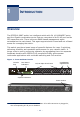
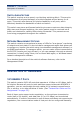
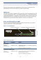
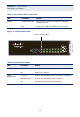
Table Of Contents
- Compliances and Safety Statements
- About This Guide
- Contents
- Tables
- Figures
- Introduction
- Installing the Switch
- Making Network Connections
- Troubleshooting
- Cables
- Specifications
- Glossary
- Index

C
HAPTER
1
| Introduction
Description of Hardware
– 27 –
Each port also supports auto-negotiation of flow control, so the switch can
automatically prevent port buffers from becoming saturated.
SFP SLOTS
The Small Form Factor Pluggable (SFP) transceiver slots are shared with four RJ-
45 ports (combination ports). In its default configuration, if an SFP transceiver
(purchased separately) is installed in a slot and has a valid link on its port, the
associated RJ-45 port is disabled and cannot be used. The switch can also be
configured to force the use of an RJ-45 port or SFP slot, as required.
PORT AND SYSTEM STATUS LEDS
The LEDs, which are located on the front panel for easy viewing, are shown
below and described in the following table.
Figure 2: Port Status LEDs
Table 1: Port Status LEDs
LED Condition Status
RJ-45 Ports
Link/ACT
(Link/Activity)
On/Blinking Green The port has a valid 10 or 100 Mbps link. Blinking
indicates activity.
Off There is no valid link on the port.
Combination Gigabit Ports
Link/ACT
(Link/Activity)
On/Blinking Green The port has a valid 10/100/1000 Mbps link.
Blinking indicates activity.
Off There is no valid link on the port.
RJ-45 Port Status LEDs
Combination Gigabit Port Status LEDs