
ECS3510-26P_Management Guide R02
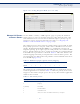
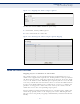
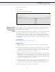
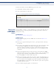
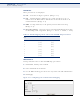
Table Of Contents
- About This Guide
- Contents
- Figures
- Tables
- Getting Started
- Web Configuration
- Using the Web Interface
- Basic Management Tasks
- Displaying System Information
- Displaying Hardware/Software Versions
- Configuring Support for Jumbo Frames
- Displaying Bridge Extension Capabilities
- Managing System Files
- Setting the System Clock
- Configuring the Console Port
- Configuring Telnet Settings
- Displaying CPU Utilization
- Displaying Memory Utilization
- Resetting the System
- Interface Configuration
- VLAN Configuration
- Address Table Settings
- Spanning Tree Algorithm
- Congestion Control
- Class of Service
- Quality of Service
- VoIP Traffic Configuration
- Security Measures
- AAA Authorization and Accounting
- Configuring User Accounts
- Web Authentication
- Network Access (MAC Address Authentication)
- Configuring HTTPS
- Configuring the Secure Shell
- Access Control Lists
- ARP Inspection
- Filtering IP Addresses for Management Access
- Configuring Port Security
- Configuring 802.1X Port Authentication
- IP Source Guard
- DHCP Snooping
- DoS Protection
- Basic Administration Protocols
- IP Configuration
- IP Services
- Multicast Filtering
- Command Line Interface
- Using the Command Line Interface
- General Commands
- System Management Commands
- SNMP Commands
- Remote Monitoring Commands
- Authentication Commands
- User Accounts
- Authentication Sequence
- RADIUS Client
- TACACS+ Client
- AAA
- Web Server
- Telnet Server
- Secure Shell
- 802.1X Port Authentication
- dot1x default
- dot1x eapol-pass-through
- dot1x system-auth-control
- dot1x intrusion-action
- dot1x max-req
- dot1x operation-mode
- dot1x port-control
- dot1x re-authentication
- dot1x timeout quiet-period
- dot1x timeout re-authperiod
- dot1x timeout supp-timeout
- dot1x timeout tx-period
- dot1x re-authenticate
- dot1x identity profile
- dot1x max-start
- dot1x pae supplicant
- dot1x timeout auth-period
- dot1x timeout held-period
- dot1x timeout start-period
- show dot1x
- Management IP Filter
- General Security Measures
- Port Security
- Network Access (MAC Address Authentication)
- network-access aging
- network-access mac-filter
- mac-authentication reauth-time
- network-access dynamic-qos
- network-access dynamic-vlan
- network-access guest-vlan
- network-access link-detection
- network-access link-detection link-down
- network-access link-detection link-up
- network-access link-detection link-up-down
- network-access max-mac-count
- network-access mode mac-authentication
- network-access port-mac-filter
- mac-authentication intrusion-action
- mac-authentication max-mac-count
- clear network-access
- show network-access
- show network-access mac-address-table
- show network- access mac-filter
- Web Authentication
- DHCP Snooping
- IP Source Guard
- ARP Inspection
- ip arp inspection
- ip arp inspection filter
- ip arp inspection log-buffer logs
- ip arp inspection validate
- ip arp inspection vlan
- ip arp inspection limit
- ip arp inspection trust
- show ip arp inspection configuration
- show ip arp inspection interface
- show ip arp inspection log
- show ip arp inspection statistics
- show ip arp inspection vlan
- Denial of Service Protection
- Access Control Lists
- Interface Commands
- Link Aggregation Commands
- Port Mirroring Commands
- Rate Limit Commands
- Automatic Traffic Control Commands
- Threshold Commands
- SNMP Trap Commands
- snmp-server enable port-traps atc broadcast-alarm- clear
- snmp-server enable port-traps atc broadcast-alarm-fire
- snmp-server enable port-traps atc broadcast-control- apply
- snmp-server enable port-traps atc broadcast-control- release
- snmp-server enable port-traps atc multicast-alarm- clear
- snmp-server enable port-traps atc multicast-alarm-fire
- snmp-server enable port-traps atc multicast-control- apply
- snmp-server enable port-traps atc multicast-control- release
- ATC Display Commands
- Address Table Commands
- Spanning Tree Commands
- spanning-tree
- spanning-tree cisco-prestandard
- spanning-tree forward-time
- spanning-tree hello-time
- spanning-tree max-age
- spanning-tree mode
- spanning-tree pathcost method
- spanning-tree priority
- spanning-tree mst configuration
- spanning-tree transmission-limit
- max-hops
- mst priority
- mst vlan
- name
- revision
- spanning-tree bpdu-filter
- spanning-tree bpdu-guard
- spanning-tree cost
- spanning-tree edge- port
- spanning-tree link-type
- spanning-tree loopback-detection
- spanning-tree loopback-detection action
- spanning-tree loopback-detection release-mode
- spanning-tree loopback-detection trap
- spanning-tree mst cost
- spanning-tree mst port-priority
- spanning-tree port-priority
- spanning-tree root-guard
- spanning-tree spanning-disabled
- spanning-tree loopback-detection release
- spanning-tree protocol-migration
- show spanning-tree
- show spanning-tree mst configuration
- VLAN Commands
- Class of Service Commands
- Quality of Service Commands
- Multicast Filtering Commands
- IGMP Snooping
- ip igmp snooping
- ip igmp snooping proxy-reporting
- ip igmp snooping querier
- ip igmp snooping router-alert-option- check
- ip igmp snooping router-port-expire- time
- ip igmp snooping tcn-flood
- ip igmp snooping tcn-query-solicit
- ip igmp snooping unregistered-data- flood
- ip igmp snooping unsolicited-report- interval
- ip igmp snooping version
- ip igmp snooping version-exclusive
- ip igmp snooping vlan general-query- suppression
- ip igmp snooping vlan immediate- leave
- ip igmp snooping vlan last-memb- query-count
- ip igmp snooping vlan last-memb- query-intvl
- ip igmp snooping vlan mrd
- ip igmp snooping vlan proxy-address
- ip igmp snooping vlan query-interval
- ip igmp snooping vlan query-resp- intvl
- ip igmp snooping vlan static
- show ip igmp snooping
- show ip igmp snooping mrouter
- show ip igmp snooping group
- Static Multicast Routing
- IGMP Filtering and Throttling
- Multicast VLAN Registration
- IGMP Snooping
- LLDP Commands
- lldp
- lldp holdtime-multiplier
- lldp med-fast-start- count
- lldp notification-interval
- lldp refresh-interval
- lldp reinit-delay
- lldp tx-delay
- lldp admin-status
- lldp basic-tlv management-ip- address
- lldp basic-tlv port-description
- lldp basic-tlv system-capabilities
- lldp basic-tlv system-description
- lldp basic-tlv system-name
- lldp dot1-tlv proto-ident
- lldp dot1-tlv proto-vid
- lldp dot1-tlv pvid
- lldp dot1-tlv vlan-name
- lldp dot3-tlv link-agg
- lldp dot3-tlv max-frame
- lldp med-location civic-addr
- lldp med-notification
- lldp med-tlv ext-poe
- lldp med-tlv inventory
- lldp med-tlv location
- lldp med-tlv med-cap
- lldp med-tlv network-policy
- lldp notification
- show lldp config
- show lldp info local-device
- show lldp info remote-device
- show lldp info statistics
- Domain Name Service Commands
- DHCP Commands
- IP Interface Commands
- Appendices
- Glossary
- Command List
- Index

C
HAPTER
10
| Class of Service
Layer 2 Queue Settings
– 243 –
Figure 116: Setting the Queue Mode (Strict and WRR)
MAPPING COS VALUES
TO EGRESS QUEUES
Use the Traffic > Priority > PHB to Queue page to specify the hardware
output queues to use based on the internal per-hop behavior value. (For
more information on exact manner in which the ingress priority tags are
mapped to egress queues for internal processing, see "Mapping CoS
Priorities to Internal DSCP Values" on page 249).
The switch processes Class of Service (CoS) priority tagged traffic by using
four priority queues for each port, with service schedules based on strict
priority, Weighted Round-Robin (WRR), or a combination of strict and
weighted queuing. Up to eight separate traffic priorities are defined in IEEE
802.1p. Default priority levels are assigned according to recommendations
in the IEEE 802.1p standard as shown in Table 14. This table indicates the
default mapping of internal per-hop behavior to the hardware queues. The
actual mapping may differ if the CoS priorities to internal DSCP values have
been modified (page 249).
The priority levels recommended in the IEEE 802.1p standard for various
network applications are shown in Table 15. However, priority levels can be
mapped to the switch’s output queues in any way that benefits application
traffic for the network.
Table 14: IEEE 802.1p Egress Queue Priority Mapping
Priority 01234567
Queue 10012233
Table 15: CoS Priority Levels
Priority Level Traffic Type
1 Background
2(Spare)
0 (default) Best Effort
3 Excellent Effort
4 Controlled Load
5 Video, less than 100 milliseconds latency and jitter