ECS3510-26P 26-Port Layer 2 Gigabit Ethernet Switch Installation Guide www.edge-core.
Installation Guide ECS3510-26P MANAGED 26-PORT FE POE SWITCH Layer 2 Gigabit Ethernet Switch, with 24 10/100BASE-T (RJ-45) PoE Ports, and 2 Gigabit Combination Ports (RJ-45/SFP) E072013-KS-R01 149100000220A
How to Use This Guide This guide includes detailed information on the switch hardware, including network ports, power, cabling requirements, as well as plug-in modules and transceivers. This guide also provides general installation guidelines and recommended procedures. To deploy this switch effectively and ensure troublefree operation it is recommended to first read the relevant sections in this guide so that you are familiar with all its hardware components.
How to Use This Guide ◆ Chapter 5 - Port Connections — Includes information on network interfaces, installing optional transceivers, and cabling specifications. ◆ Chapter 6 - Switch Management — Connecting to the switch for management, and information on the system status LEDs. ◆ Appendix A - Troubleshooting — Information for troubleshooting switch installation and operation.
Contents How to Use This Guide 3 Contents 5 Figures 7 Tables 8 1 Switch Description 9 Overview 9 Key Hardware Components Key Technical Specifications 2 Installation Overview 10 12 14 Package Contents 14 Switch Installation Tasks 15 3 Switch Chassis 19 General Installation Guidelines 19 How to Install the Switch in a Rack 20 Rack-Mounting Items 20 Rack-Mount Procedure 20 How to Install the Switch on a Shelf or Desktop.
Contents Understanding the Port Status LEDs 31 How to Install an SFP Transceiver 32 How to Connect to Twisted-Pair Copper Ports 34 Copper Cabling Guidelines 34 10/100BASE-TX Pin Assignments 34 1000BASE-T Assignments 35 Power-over-Ethernet 36 Connection Procedure 36 How to Connect to SFP Fiber Optic Ports Connection Procedure 6 Switch Management 38 39 41 Understanding the System Status LEDs 42 How to Connect to the Console Port 43 How to Reset the Switch 45 A Troubleshooting 46 D
Figures Figure 1: Front Panel ECS3510-26P 10 Figure 2: Rear Panel 11 Figure 3: Installing the Switch in a Rack 15 Figure 4: Connecting AC Power 16 Figure 5: System LEDs 17 Figure 6: Console Port 17 Figure 7: Making a Connection to an SFP Port 18 Figure 8: Attaching the Brackets 21 Figure 9: Installing the Switch in a Rack 21 Figure 10: Attaching the Adhesive Feet 22 Figure 11: Switch Cooling 23 Figure 12: AC Power Supply Socket 25 Figure 13: Grounding Terminal 26 Figure 14: AC Pow
Tables Table 1: Key Technical Specifications 12 Table 2: AC Power Supply Specifications 25 Table 3: Port Status LEDs 31 Table 4: Maximum Twisted-Pair Copper Cable Lengths 34 Table 5: 10/100BASE-TX MDI and MDI-X Port Pinouts 35 Table 6: 1000BASE-T MDI and MDI-X Port Pinouts 35 Table 7: Maximum Gigabit Ethernet Fiber Cable Lengths 38 Table 8: Maximum Fast Ethernet Fiber Cable Lengths 38 Table 9: System Status LEDs 42 Table 10: Console Cable Wiring 43 Table 11: Using the Reset Button 45
1 Switch Description This chapter includes these sections: ◆ “Overview” on page 9 ◆ “Key Technical Specifications” on page 12 Overview Thank you for choosing the ECS3510-26P switch system. Your switch is built with leading-edge technology to deliver reliable high-performance connectivity for your data network.
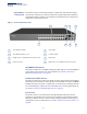
Chapter 1 | Switch Description Overview Key Hardware The switch consists of several key hardware components. This manual describes Components each specific component, or related components, together with their installation requirements and procedures in each chapter. To understand each component in detail, refer to the relevant section.
Chapter 1 | Switch Description Overview Mode Button Pressing the Mode button on the front panel will change the Diag LED and the PoEenabled port LEDs to display PoE status. For more information, see “Understanding the System Status LEDs” on page 42. System LEDs For information on system status LED indicators, see “Understanding the System Status LEDs” on page 42. Port LEDs For information on port status LED indicators, see “Understanding the Port Status LEDs” on page 31.
Chapter 1 | Switch Description Key Technical Specifications Reset Button Pressing the reset button on the rear panel causes the switch to execute a hard reset. For more information, see “How to Reset the Switch” on page 45. Key Technical Specifications The following table contains key system specifications for the switch.
Chapter 1 | Switch Description Key Technical Specifications – 13 –
2 Installation Overview This chapter includes these sections: ◆ “Package Contents” on page 14 ◆ “Switch Installation Tasks” on page 15 Package Contents After unpacking the switch, check the contents to be sure you have received all the components.
Chapter 2 | Installation Overview Switch Installation Tasks Switch Installation Tasks Follow these tasks to install the switch in your network. For full details on each task, go to the relevant chapter or section by clicking on the link. Caution: Before installing your switch, first review all the safety statements and guidelines in the Regulatory and Safety Information document.
Chapter 2 | Installation Overview Switch Installation Tasks Task 3 Connect AC Power to Power On Connect the power cord to the AC socket on the switch and to a grounded, 3-pin, AC power source. Go to the chapter “Power and Grounding” Figure 4: Connecting AC Power 2 1 1 Task 4 Supplied AC Power cord. 2 Connect an external AC power source to the AC power socket of the switch using the supplied AC power cord. Verify Switch Operation Verify basic switch operation by checking the system LEDs.
Chapter 2 | Installation Overview Switch Installation Tasks Figure 5: System LEDs 1 1 Task 5 System Status LEDs. Make Initial Configuration Changes At this point you may need to make a few basic switch configuration changes before connecting to the network. It is suggested to connect to the switch console port to perform this task. The serial port’s configuration requirements are as follows: 115200 bps, 8 characters, no parity, one stop bit, 8 data bits, and no flow control.
Chapter 2 | Installation Overview Switch Installation Tasks For information on initial switch configuration: Refer to the Management Guide. Task 6 Install Transceivers and Connect Cables Install SFP transceivers and connect network cables to port interfaces: ◆ For RJ-45 ports, use 100-ohm category 3 or better ethernet cable for 10BASE-T connections, use 100-ohm category 5 or better ethernet cable for 100BASE-TX and 1000BASE-T connections.
3 Switch Chassis The switch is designed to be installed in a standard 19-inch equipment rack. Before continuing with switch installation, first review the general guidelines and switch cooling requirements in this chapter. This chapter includes these sections: ◆ “General Installation Guidelines” on page 19 ◆ “How to Install the Switch in a Rack” on page 20 ◆ “How to Install the Switch on a Shelf or Desktop.
Chapter 3 | Switch Chassis How to Install the Switch in a Rack How to Install the Switch in a Rack When rack mounting the switch, pay particular attention to the following factors: ◆ Rack Types: You can use any standard EIA 19-inch equipment rack with either two or four posts. The bracket hole pattern should be spaced 1U (1.75 in. or 4.45 cm) apart.
Chapter 3 | Switch Chassis How to Install the Switch in a Rack 1. Attach the brackets to the device using the screws provided in the Bracket Mounting Kit. Figure 8: Attaching the Brackets 1 1 Use the screws provided in the Bracket Mounting Kit. 2. Following your rack plan, mark the holes in the rack where the switch will be installed. 3. One person should lift the switch into the rack so that it is aligned with the marked holes. 4.
Chapter 3 | Switch Chassis How to Install the Switch on a Shelf or Desktop. 5. If installing a single switch only, go to “Power and Grounding” on page 25. 6. If installing multiple switches, repeat steps 1 to 4 to mount the switches following your rack plan. How to Install the Switch on a Shelf or Desktop. The switch can be installed on any flat surface such as a desktop or shelf. To mount the switch on a flat surface follow these steps: 1. Attach the four adhesive feet to the bottom of the first switch.
Chapter 3 | Switch Chassis Switch Cooling Requirements Switch Cooling Requirements Wherever the switch is located, be sure to pay close attention to switch cooling requirements. The location should be well ventilated and provide unrestricted airflow at the front, back, and sides of the switch. If the airflow is insufficient, it may cause the switch to overheat and possibly fail. The following figure shows the cool air intake and the hot air exhaust airflow into and from the switch.
Chapter 3 | Switch Chassis Switch Cooling Requirements – 24 –
4 Power and Grounding This chapter focuses on how to connect AC power to the switch and how to poweron the switch. This chapter includes this sections: ◆ “Switch Power Supply” on page 25 ◆ “Grounding the Chassis” on page 26 ◆ “How to Connect to AC Power” on page 27 Switch Power Supply The switch requires power from an external AC power supply that can provide 100 to 240 VAC, 50-60 Hz. A standard AC power socket is located on the rear panel of the switch. The power socket is for the AC power cord.
Chapter 4 | Power and Grounding Grounding the Chassis Grounding the Chassis The rear panel of the switch chassis includes a single hole grounding terminal. It must be connected to ground to ensure proper operation and to meet electromagnetic interference (EMI) and safety requirements. Figure 13: Grounding Terminal 2 1 1 2 Grounding Wire Grounding Terminal Before powering on the switch, ground the switch to earth as described below. 1.
Chapter 4 | Power and Grounding How to Connect to AC Power How to Connect to AC Power To supply AC power to the switch, first verify that the external AC power supply can provide 100 to 240 VAC, 50-60 Hz, 3.0 A minimum. To connect the switch to a power source: 1. Plug the power cord into a grounded, 3-pin, AC power source. Figure 14: AC Power Cord and Power Socket 2 1 1 2 AC Power Cord AC Power Socket 2.
Chapter 4 | Power and Grounding How to Connect to AC Power – 28 –
5 Port Connections This chapter focuses on making connections to switch network interfaces, including how to install optional transceivers, and details on network cable specifications. The switch features 24 10/100BASE-T RJ-45 ports and two Gigabit SFP transceiver slots in combination with two 1000BASE-T RJ-45 ports. The sections that follow describe these interfaces.
Chapter 5 | Port Connections Cable Labeling and Connection Records Cable Labeling and Connection Records When planning a network installation, it is essential to label the opposing ends of cables and to record where each cable is connected. Doing so will enable you to easily locate inter-connected devices, isolate faults and change your topology without need for unnecessary time consumption.
Chapter 5 | Port Connections Understanding the Port Status LEDs Understanding the Port Status LEDs The switch includes LED indicators for each port to indicate link status and network activity. The port LEDs are shown below and described in the following table.
Chapter 5 | Port Connections How to Install an SFP Transceiver How to Install an SFP Transceiver The switch provides slots for optional SFP transceivers. The supported transceiver types are listed below: ◆ 1000BASE-SX ◆ 1000BASE-LX ◆ 1000BASE-LH ◆ 100BASE-FX ◆ 1000BASE-T Note: SFP transceivers are hot-swappable. The switch does not need to be powered off before installing or removing a transceiver. Note: SFP transceivers are not provided in the switch package.
Chapter 5 | Port Connections How to Install an SFP Transceiver Figure 16: Inserting an SFP Transceiver into a Slot 1 1 SFP Transceiver Note: To remove a transceiver: First disconnect the network cable, then pull the tab to remove the transceiver from the slot.
Chapter 5 | Port Connections How to Connect to Twisted-Pair Copper Ports How to Connect to Twisted-Pair Copper Ports The RJ-45 ports on the switch support automatic MDI/MDI-X pinout configuration, which enables you to use standard straight-through twisted-pair cables to connect to any other network device (PCs, servers, switches, routers, or hubs). The connection requires an unshielded twisted-pair (UTP) or shielded twisted-pair (STP) cable with RJ-45 connectors at both ends.
Chapter 5 | Port Connections How to Connect to Twisted-Pair Copper Ports Figure 17: RJ-45 Connector 1 1 RJ-45 Pin Numbers Table 5: 10/100BASE-TX MDI and MDI-X Port Pinouts Pin MDI Signal Namea MDI-X Signal Name 1 Transmit Data plus (TD+) -52V power (Negative Vport) Receive Data plus (RD+) GND (Positive Vport) 2 Transmit Data minus (TD-) -52V power (Negative Vport) Receive Data minus (RD-) GND (Positive Vport) 3 Receive Data plus (RD+) GND (Positive Vport) Transmit Data plus (TD+) -52V power (N
Chapter 5 | Port Connections How to Connect to Twisted-Pair Copper Ports Table 6: 1000BASE-T MDI and MDI-X Port Pinouts (Continued) Pin MDI Signal Name MDI-X Signal Name 4 Bi-directional Pair C Plus (BI_DC+) Bi-directional Pair D Plus (BI_DD+) 5 Bi-directional Pair C Minus (BI_DC-) Bi-directional Pair D Minus (BI_DD-) 6 Bi-directional Pair B Minus (BI_DB-) Bi-directional Pair A Minus (BI_DA-) 7 Bi-directional Pair D Plus (BI_DD+) Bi-directional Pair C Plus (BI_DC+) 8 Bi-directional Pair D M
Chapter 5 | Port Connections How to Connect to Twisted-Pair Copper Ports Figure 18: Making Twisted-Pair Connections 1 2 1 1000BASE-T RJ-45 Port 2 Category 5,5e or 6 Cable 2. Attach the other end to an available port on the switch. Make sure each twisted pair cable does not exceed 100 meters (328 ft) in length. Note: When connecting to RJ-45 ports 25 or 26, verify the corresponding combination SFP port is not in use.
Chapter 5 | Port Connections How to Connect to SFP Fiber Optic Ports How to Connect to SFP Fiber Optic Ports The switch provides two slots for SFP-compliant fiber-optic transceivers. Note that all 1000BASE fiber optic ports operate at 1 Gbps full duplex. The 100BASE fiber optic ports operate at 100 Mbps full duplex.
Chapter 5 | Port Connections How to Connect to SFP Fiber Optic Ports Connection Procedure Follow these steps to connect cables to SFP transceiver ports. Warning: This switch uses lasers to transmit signals over fiber optic cable. The lasers are compliant with the requirements of a Class 1 Laser Product and are inherently eye safe in normal operation. However, you should never look directly at a transmit port when it is powered on.
Chapter 5 | Port Connections How to Connect to SFP Fiber Optic Ports Note: Be sure to secure cables properly and route them away from the switch without exceeding the minimum bending radius for fiber cables (typically a few inches). Use cable ties to bundle cables together and secure coiled loops of excess cable. Do not let cables hang free supporting their own weight or pull in any way that puts stress on the connectors.
6 Switch Management The switch includes a management agent that allows you to configure or monitor the switch using its embedded management software. To manage the switch, you can make a direct connection to the console port (out-of-band), or you can manage it through a network connection (in-band) using Telnet, Secure Shell (SSH), a web browser, or SNMP-based network management software. For a detailed description of the switch’s software features, refer to the Management Guide.
Chapter 6 | Switch Management Understanding the System Status LEDs Understanding the System Status LEDs The switch includes a display panel of key system LED indicators. The LEDs, which are located on the front panel, are shown below and described in the following table. Figure 20: System Status LEDs 1 1 System Status LEDs ( Table 9: System Status LEDs LED Condition Status PWR On Green Internal power operating normally. Off No AC power is connected or the internal power supply has failed.
Chapter 6 | Switch Management How to Connect to the Console Port How to Connect to the Console Port The RJ-45 Console port on the front panel of the switch is used to connect a console device to the switch for out-of-band console configuration. The console device can be a PC or workstation running a VT-100 terminal emulator, or a VT-100 terminal. A console cable is supplied with the switch for connecting to a PC’s RS232 serial DB-9 DTE (COM) port.
Chapter 6 | Switch Management How to Connect to the Console Port ◆ Stop bit—One ◆ Data bits—8 ◆ Flow control—None Figure 22: Console Port Connection Follow these steps to connect to the Console port: 1. Connect one end of the included RJ-45 to DB-9 serial cable to a DB-9 COM port connector on a management PC. 2. Plug in the RJ-45 end of the serial cable to the Console port on the switch. 3.
Chapter 6 | Switch Management How to Reset the Switch ■ User — guest ■ Password — guest Note that the guest default user login will only allow a user to view switch parameter data. For a detailed description of connecting to the console and using the switch’s command line interface (CLI), refer to the Management Guide.
A Troubleshooting Diagnosing LED Indicators Table 12: Troubleshooting Chart Symptom Action PWR LED is Off ◆ ◆ ◆ DIAG LED is blinking Amber ◆ Link/Act LED is Off ◆ ◆ ◆ ◆ ◆ ◆ Check connections between the switch, the power cord, and the AC power outlet. Check the AC power outlet is supplying 110-240 VAC. Contact your dealer for assistance. Power cycle the switch to try and clear the condition. If the condition does not clear, contact your dealer for assistance.
Chapter A | Troubleshooting Power Problems Power Problems If a power indicator does not turn on when the power cord is plugged in, you may have a problem with the power outlet, power cord, or internal power supply. However, if the switch shuts down after operating for a continuous period, check for loose power connections, power losses or surges at the power outlet. If you still cannot isolate the problem, the internal power supply may be defective.
Index Numerics 10 Mbps collision domain 38 10 Mbps connectivity rules 38 10/100 PIN assignments 34 1000BASE fiber cable lengths 38 1000BASE-T PIN assignments 35 10BASE-T cable lengths 38 Ethernet connectivity rules 38 Ethernet Port connecting to 34 F factory default settings 45 I A adhesive feet, attaching 22 air flow requirements 19 B brackets, attaching 21 buffer size 12 in-band access 47 indicators, LED 31, 42 installation power requirements 19 site requirements 19 installation troubleshooting 47 i
Index R reset button 45 resetting the switch 45 RJ-45 port connecting to 34 rubber foot pads, attaching 22 S screws for rack mounting 20 SFP port connection procedure 39 installing transceiver 32 site selelction 19 specifications environmental 12 status LEDs 31, 42 surge suppressor, using 19 W web-based management 41 – 49 –
Declaration of Conformity (DoC) can be obtained from www.edge-core.