
Web Management Guide-R05
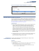
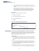
Table Of Contents
- How to Use This Guide
- Contents
- Figures
- Tables
- Getting Started
- Web Configuration
- Using the Web Interface
- Basic Management Tasks
- Displaying System Information
- Displaying Hardware/Software Versions
- Configuring Support for Jumbo Frames
- Displaying Bridge Extension Capabilities
- Managing System Files
- Setting the System Clock
- Configuring the Console Port
- Configuring Telnet Settings
- Displaying CPU Utilization
- Configuring CPU Guard
- Displaying Memory Utilization
- Resetting the System
- Using Cloud Management
- Interface Configuration
- VLAN Configuration
- Address Table Settings
- Spanning Tree Algorithm
- Congestion Control
- Class of Service
- Quality of Service
- VoIP Traffic Configuration
- Security Measures
- AAA (Authentication, Authorization and Accounting)
- Configuring User Accounts
- Web Authentication
- Network Access (MAC Address Authentication)
- Configuring HTTPS
- Configuring the Secure Shell
- Access Control Lists
- Filtering IP Addresses for Management Access
- Configuring Port Security
- Configuring 802.1X Port Authentication
- DoS Protection
- DHCP Snooping
- IPv4 Source Guard
- ARP Inspection
- Basic Administration Protocols
- Configuring Event Logging
- Link Layer Discovery Protocol
- Simple Network Management Protocol
- Configuring Global Settings for SNMP
- Setting the Local Engine ID
- Specifying a Remote Engine ID
- Setting SNMPv3 Views
- Configuring SNMPv3 Groups
- Setting Community Access Strings
- Configuring Local SNMPv3 Users
- Configuring Remote SNMPv3 Users
- Specifying Trap Managers
- Creating SNMP Notification Logs
- Showing SNMP Statistics
- Remote Monitoring
- Switch Clustering
- Setting a Time Range
- LBD Configuration
- Smart Pair Configuration
- Multicast Filtering
- Overview
- Layer 2 IGMP (Snooping and Query for IPv4)
- Configuring IGMP Snooping and Query Parameters
- Specifying Static Interfaces for a Multicast Router
- Assigning Interfaces to Multicast Services
- Setting IGMP Snooping Status per Interface
- Filtering IGMP Query Packets and Multicast Data
- Displaying Multicast Groups Discovered by IGMP Snooping
- Displaying IGMP Snooping Statistics
- Filtering and Throttling IGMP Groups
- MLD Snooping (Snooping and Query for IPv6)
- Filtering and Throttling MLD Groups
- Filtering MLD Query Packets on an Interface
- IP Tools
- IP Configuration
- General IP Routing
- Unicast Routing
- Overview
- Configuring the Routing Information Protocol
- Configuring General Protocol Settings
- Clearing Entries from the Routing Table
- Specifying Network Interfaces
- Specifying Passive Interfaces
- Specifying Static Neighbors
- Configuring Route Redistribution
- Specifying an Administrative Distance
- Configuring Network Interfaces for RIP
- Displaying RIP Interface Settings
- Displaying Peer Router Information
- Resetting RIP Statistics
- IP Services
- Appendices
- Glossary
- Index

Chapter 16
| IP Configuration
Setting the Switch’s IP Address (IP Version 6)
– 485 –
Discovery to discover each other's presence, to determine each other's link-
layer addresses, to find routers and to maintain reachability information about
the paths to active neighbors. The key parameters used to facilitate this process
are the number of attempts made to verify whether or not a duplicate address
exists on the same network segment, and the interval between neighbor
solicitations used to verify reachability information.
Parameters
These parameters are displayed:
◆ VLAN – ID of a configured VLAN which is to be used for management access, or
as a standard interface for a subnet. By default, all ports on the switch are
members of VLAN 1. However, the management station can be attached to a
port belonging to any VLAN, as long as that VLAN has been assigned an IP
address. (Range: 1-4094)
◆ Address Autoconfig – Enables stateless autoconfiguration of an IPv6 address
on an interface and enables IPv6 functionality on that interface. The network
portion of the address is based on prefixes received in IPv6 router
advertisement messages, and the host portion is automatically generated
using the modified EUI-64 form of the interface identifier (i.e., the switch’s MAC
address).
■
If a link local address has not yet been assigned to this interface, this
command will dynamically generate one. The link-local address is made
with an address prefix in the range of FE80~FEBF and a host portion based
the switch’s MAC address in modified EUI-64 format. It will also generate a
global unicast address if a global prefix is included in received router
advertisements.
■
When DHCPv6 is started, the switch may attempt to acquire an IP address
prefix through stateful address autoconfiguration. If router advertisements
have the “other stateful configuration” flag set, the switch will attempt to
acquire other non-address configuration information (such as a default
gateway).
■
If auto-configuration is not selected, then an address must be manually
configured using the Add IPv6 Address page described below.
◆ Enable IPv6 Explicitly – Enables IPv6 on an interface and assigns it a link-local
address. Note that when an explicit address is assigned to an interface, IPv6 is
automatically enabled, and cannot be disabled until all assigned addresses
have been removed. (Default: Disabled)
Disabling this parameter does not disable IPv6 for an interface that has been
explicitly configured with an IPv6 address.
◆ MTU – Sets the size of the maximum transmission unit (MTU) for IPv6 packets
sent on an interface. (Range: 1280-65535 bytes; Default: 1500 bytes)
■
The maximum value set in this field cannot exceed the MTU of the physical
interface, which is currently fixed at 1500 bytes.