
Web Management Guide-R05
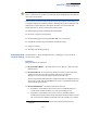
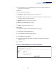
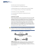
Table Of Contents
- How to Use This Guide
- Contents
- Figures
- Tables
- Getting Started
- Web Configuration
- Using the Web Interface
- Basic Management Tasks
- Displaying System Information
- Displaying Hardware/Software Versions
- Configuring Support for Jumbo Frames
- Displaying Bridge Extension Capabilities
- Managing System Files
- Setting the System Clock
- Configuring the Console Port
- Configuring Telnet Settings
- Displaying CPU Utilization
- Configuring CPU Guard
- Displaying Memory Utilization
- Resetting the System
- Using Cloud Management
- Interface Configuration
- VLAN Configuration
- Address Table Settings
- Spanning Tree Algorithm
- Congestion Control
- Class of Service
- Quality of Service
- VoIP Traffic Configuration
- Security Measures
- AAA (Authentication, Authorization and Accounting)
- Configuring User Accounts
- Web Authentication
- Network Access (MAC Address Authentication)
- Configuring HTTPS
- Configuring the Secure Shell
- Access Control Lists
- Filtering IP Addresses for Management Access
- Configuring Port Security
- Configuring 802.1X Port Authentication
- DoS Protection
- DHCP Snooping
- IPv4 Source Guard
- ARP Inspection
- Basic Administration Protocols
- Configuring Event Logging
- Link Layer Discovery Protocol
- Simple Network Management Protocol
- Configuring Global Settings for SNMP
- Setting the Local Engine ID
- Specifying a Remote Engine ID
- Setting SNMPv3 Views
- Configuring SNMPv3 Groups
- Setting Community Access Strings
- Configuring Local SNMPv3 Users
- Configuring Remote SNMPv3 Users
- Specifying Trap Managers
- Creating SNMP Notification Logs
- Showing SNMP Statistics
- Remote Monitoring
- Switch Clustering
- Setting a Time Range
- LBD Configuration
- Smart Pair Configuration
- Multicast Filtering
- Overview
- Layer 2 IGMP (Snooping and Query for IPv4)
- Configuring IGMP Snooping and Query Parameters
- Specifying Static Interfaces for a Multicast Router
- Assigning Interfaces to Multicast Services
- Setting IGMP Snooping Status per Interface
- Filtering IGMP Query Packets and Multicast Data
- Displaying Multicast Groups Discovered by IGMP Snooping
- Displaying IGMP Snooping Statistics
- Filtering and Throttling IGMP Groups
- MLD Snooping (Snooping and Query for IPv6)
- Filtering and Throttling MLD Groups
- Filtering MLD Query Packets on an Interface
- IP Tools
- IP Configuration
- General IP Routing
- Unicast Routing
- Overview
- Configuring the Routing Information Protocol
- Configuring General Protocol Settings
- Clearing Entries from the Routing Table
- Specifying Network Interfaces
- Specifying Passive Interfaces
- Specifying Static Neighbors
- Configuring Route Redistribution
- Specifying an Administrative Distance
- Configuring Network Interfaces for RIP
- Displaying RIP Interface Settings
- Displaying Peer Router Information
- Resetting RIP Statistics
- IP Services
- Appendices
- Glossary
- Index

Chapter 5
| VLAN Configuration
IEEE 802.1Q VLANs
– 150 –
This switch supports the following VLAN features:
◆ Up to 4094 VLANs based on the IEEE 802.1Q standard
◆ Distributed VLAN learning across multiple switches using explicit tagging.
◆ Port overlapping, allowing a port to participate in multiple VLANs
◆ End stations can belong to multiple VLANs
◆ Passing traffic between VLAN-aware and VLAN-unaware devices
◆ Priority tagging
Assigning Ports to VLANs
Before enabling VLANs for the switch, you must first assign each port to the VLAN
group(s) in which it will participate. By default all ports are assigned to VLAN 1 as
untagged ports. Add a port as a tagged port if you want it to carry traffic for one or
more VLANs, and any intermediate network devices or the host at the other end of
the connection supports VLANs. Then assign ports on the other VLAN-aware
network devices along the path that will carry this traffic to the same VLAN(s),
either manually or dynamically using GVRP. However, if you want a port on this
switch to participate in one or more VLANs, but none of the intermediate network
devices nor the host at the other end of the connection supports VLANs, then you
should add this port to the VLAN as an untagged port.
Note:
VLAN-tagged frames can pass through VLAN-aware or VLAN-unaware
network interconnection devices, but the VLAN tags should be stripped off before
passing it on to any end-node host that does not support VLAN tagging.
Figure 75: VLAN Compliant and VLAN Non-compliant Devices
VLAN Classification – When the switch receives a frame, it classifies the frame in
one of two ways. If the frame is untagged, the switch assigns the frame to an
associated VLAN (based on the default VLAN ID of the receiving port). But if the
frame is tagged, the switch uses the tagged VLAN ID to identify the port broadcast
domain of the frame.
VA
VA: VLAN Aware
VU: VLAN Unaware
VA
tagged frames
VA VUVA
tagged
frames
untagged
frames