
Web Management Guide-R05
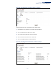
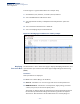
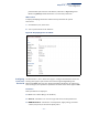
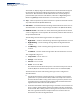
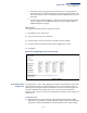
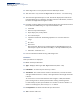
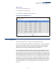
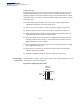
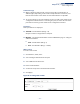
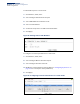
Table Of Contents
- How to Use This Guide
- Contents
- Figures
- Tables
- Getting Started
- Web Configuration
- Using the Web Interface
- Basic Management Tasks
- Displaying System Information
- Displaying Hardware/Software Versions
- Configuring Support for Jumbo Frames
- Displaying Bridge Extension Capabilities
- Managing System Files
- Setting the System Clock
- Configuring the Console Port
- Configuring Telnet Settings
- Displaying CPU Utilization
- Configuring CPU Guard
- Displaying Memory Utilization
- Resetting the System
- Using Cloud Management
- Interface Configuration
- VLAN Configuration
- Address Table Settings
- Spanning Tree Algorithm
- Congestion Control
- Class of Service
- Quality of Service
- VoIP Traffic Configuration
- Security Measures
- AAA (Authentication, Authorization and Accounting)
- Configuring User Accounts
- Web Authentication
- Network Access (MAC Address Authentication)
- Configuring HTTPS
- Configuring the Secure Shell
- Access Control Lists
- Filtering IP Addresses for Management Access
- Configuring Port Security
- Configuring 802.1X Port Authentication
- DoS Protection
- DHCP Snooping
- IPv4 Source Guard
- ARP Inspection
- Basic Administration Protocols
- Configuring Event Logging
- Link Layer Discovery Protocol
- Simple Network Management Protocol
- Configuring Global Settings for SNMP
- Setting the Local Engine ID
- Specifying a Remote Engine ID
- Setting SNMPv3 Views
- Configuring SNMPv3 Groups
- Setting Community Access Strings
- Configuring Local SNMPv3 Users
- Configuring Remote SNMPv3 Users
- Specifying Trap Managers
- Creating SNMP Notification Logs
- Showing SNMP Statistics
- Remote Monitoring
- Switch Clustering
- Setting a Time Range
- LBD Configuration
- Smart Pair Configuration
- Multicast Filtering
- Overview
- Layer 2 IGMP (Snooping and Query for IPv4)
- Configuring IGMP Snooping and Query Parameters
- Specifying Static Interfaces for a Multicast Router
- Assigning Interfaces to Multicast Services
- Setting IGMP Snooping Status per Interface
- Filtering IGMP Query Packets and Multicast Data
- Displaying Multicast Groups Discovered by IGMP Snooping
- Displaying IGMP Snooping Statistics
- Filtering and Throttling IGMP Groups
- MLD Snooping (Snooping and Query for IPv6)
- Filtering and Throttling MLD Groups
- Filtering MLD Query Packets on an Interface
- IP Tools
- IP Configuration
- General IP Routing
- Unicast Routing
- Overview
- Configuring the Routing Information Protocol
- Configuring General Protocol Settings
- Clearing Entries from the Routing Table
- Specifying Network Interfaces
- Specifying Passive Interfaces
- Specifying Static Neighbors
- Configuring Route Redistribution
- Specifying an Administrative Distance
- Configuring Network Interfaces for RIP
- Displaying RIP Interface Settings
- Displaying Peer Router Information
- Resetting RIP Statistics
- IP Services
- Appendices
- Glossary
- Index

Chapter 4
| Interface Configuration
Port Configuration
– 115 –
■
Threshold events are triggered as described above to avoid a hysteresis
effect which would continuously trigger event messages if the power level
were to fluctuate just above and below either the high threshold or the low
threshold.
■
Trap messages configured by this command are sent to any management
station configured as an SNMP trap manager using the Administration >
SNMP (Configure Trap) page.
Web Interface
To configure threshold values for optical transceivers:
1. Click Interface, Port, Transceiver.
2. Select a port from the scroll-down list.
3. Set the switch to send a trap based on default or manual settings.
4. Set alarm and warning thresholds if manual configuration is used.
5. Click Apply.
Figure 42: Configuring Transceiver Thresholds
Performing Cable
Diagnostics
Use the Interface > Port > Cable Test page to test the cable attached to a port. The
cable test will check for any cable faults (short, open, etc.). If a fault is found, the
switch reports the length to the fault. Otherwise, it reports the cable length. It can
be used to determine the quality of the cable, connectors, and terminations.
Problems such as opens, shorts, and cable impedance mismatch can be diagnosed
with this test.
Command Usage
◆ Cable diagnostics are performed using Time Domain Reflectometry (TDR).
TDR detects a cable fault by sending a signal through the cable and reading the
signal that is reflected back. TDR can only determine if a link is valid or faulty.