
Web Management Guide-R07
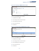
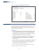
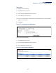
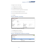
Table Of Contents
- How to Use This Guide
- Contents
- Figures
- Tables
- Getting Started
- Introduction
- Key Features
- Description of Software Features
- Configuration Backup and Restore
- Authentication
- Access Control Lists
- Port Configuration
- Rate Limiting
- Port Mirroring
- Port Trunking
- Storm Control
- Static MAC Addresses
- IP Address Filtering
- IEEE 802.1D Bridge
- Store-and-Forward Switching
- Spanning Tree Algorithm
- Virtual LANs
- IEEE 802.1Q Tunneling (QinQ)
- Traffic Prioritization
- Quality of Service
- IP Routing
- Address Resolution Protocol
- Multicast Filtering
- Link Layer Discovery Protocol
- System Defaults
- Introduction
- Web Configuration
- Using the Web Interface
- Basic Management Tasks
- Displaying System Information
- Displaying Hardware/Software Versions
- Configuring Support for Jumbo Frames
- Displaying Bridge Extension Capabilities
- Managing System Files
- Setting the System Clock
- Configuring the Console Port
- Configuring Telnet Settings
- Displaying CPU Utilization
- Configuring CPU Guard
- Displaying Memory Utilization
- Resetting the System
- Using Cloud Management
- Interface Configuration
- VLAN Configuration
- Address Table Settings
- Spanning Tree Algorithm
- Congestion Control
- Class of Service
- Quality of Service
- VoIP Traffic Configuration
- Security Measures
- AAA (Authentication, Authorization and Accounting)
- Configuring User Accounts
- Web Authentication
- Network Access (MAC Address Authentication)
- Configuring HTTPS
- Configuring the Secure Shell
- Access Control Lists
- Filtering IP Addresses for Management Access
- Configuring Port Security
- Configuring 802.1X Port Authentication
- DoS Protection
- DHCP Snooping
- IPv4 Source Guard
- ARP Inspection
- Basic Administration Protocols
- Configuring Event Logging
- Link Layer Discovery Protocol
- Power over Ethernet
- Simple Network Management Protocol
- Configuring Global Settings for SNMP
- Setting the Local Engine ID
- Specifying a Remote Engine ID
- Setting SNMPv3 Views
- Configuring SNMPv3 Groups
- Setting Community Access Strings
- Configuring Local SNMPv3 Users
- Configuring Remote SNMPv3 Users
- Specifying Trap Managers
- Creating SNMP Notification Logs
- Showing SNMP Statistics
- Remote Monitoring
- Switch Clustering
- Setting a Time Range
- LBD Configuration
- Smart Pair Configuration
- Multicast Filtering
- Overview
- Layer 2 IGMP (Snooping and Query for IPv4)
- Configuring IGMP Snooping and Query Parameters
- Specifying Static Interfaces for a Multicast Router
- Assigning Interfaces to Multicast Services
- Setting IGMP Snooping Status per Interface
- Filtering IGMP Query Packets and Multicast Data
- Displaying Multicast Groups Discovered by IGMP Snooping
- Displaying IGMP Snooping Statistics
- Filtering and Throttling IGMP Groups
- MLD Snooping (Snooping and Query for IPv6)
- Filtering and Throttling MLD Groups
- Filtering MLD Query Packets on an Interface
- IP Tools
- IP Configuration
- General IP Routing
- Unicast Routing
- Overview
- Configuring the Routing Information Protocol
- Configuring General Protocol Settings
- Clearing Entries from the Routing Table
- Specifying Network Interfaces
- Specifying Passive Interfaces
- Specifying Static Neighbors
- Configuring Route Redistribution
- Specifying an Administrative Distance
- Configuring Network Interfaces for RIP
- Displaying RIP Interface Settings
- Displaying Peer Router Information
- Resetting RIP Statistics
- IP Services
- Appendices
- Glossary

Chapter 13
| Basic Administration Protocols
Switch Clustering
– 403 –
◆ The cluster VLAN 4093 is not configured by default. Before using clustering,
take the following actions to set up this VLAN:
1. Create VLAN 4093 (see “Configuring VLAN Groups” on page 153).
2. Add the participating ports to this VLAN (see “Adding Static Members to
VLANs” on page 156), and set them to hybrid mode, tagged members,
PVID = 1, and acceptable frame type = all.
◆ After the Commander and Members have been configured, any switch in the
cluster can be managed from the web agent by choosing the desired Member
ID from the Show Member page.
Configuring General
Settings for Clusters
Use the Administration > Cluster (Configure Global) page to create a switch cluster.
Command Usage
First be sure that clustering is enabled on the switch (the default is disabled), then
set the switch as a Cluster Commander. Set a Cluster IP Pool that does not conflict
with the network IP subnet. Cluster IP addresses are assigned to switches when
they become Members and are used for communication between Member
switches and the Commander.
Parameters
These parameters are displayed:
◆ Cluster Status – Enables or disables clustering on the switch.
(Default: Disabled)
◆ Commander Status – Enables or disables the switch as a cluster Commander.
(Default: Disabled)
◆ IP Pool – An “internal” IP address pool that is used to assign IP addresses to
Member switches in the cluster. Internal cluster IP addresses are in the form
10.x.x.member-ID. Only the base IP address of the pool needs to be set since
Member IDs can only be between 1 and 36. Note that you cannot change the
cluster IP pool when the switch is currently in Commander mode. Commander
mode must first be disabled. (Default: 10.254.254.1)
◆ Role – Indicates the current role of the switch in the cluster; either Commander,
Member, or Candidate. (Default: Candidate)
◆ Number of Members – The current number of Member switches in the cluster.
◆ Number of Candidates – The current number of Candidate switches
discovered in the network that are available to become Members.