
Web Management Guide-R07
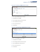
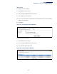
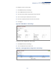
Table Of Contents
- How to Use This Guide
- Contents
- Figures
- Tables
- Getting Started
- Introduction
- Key Features
- Description of Software Features
- Configuration Backup and Restore
- Authentication
- Access Control Lists
- Port Configuration
- Rate Limiting
- Port Mirroring
- Port Trunking
- Storm Control
- Static MAC Addresses
- IP Address Filtering
- IEEE 802.1D Bridge
- Store-and-Forward Switching
- Spanning Tree Algorithm
- Virtual LANs
- IEEE 802.1Q Tunneling (QinQ)
- Traffic Prioritization
- Quality of Service
- IP Routing
- Address Resolution Protocol
- Multicast Filtering
- Link Layer Discovery Protocol
- System Defaults
- Introduction
- Web Configuration
- Using the Web Interface
- Basic Management Tasks
- Displaying System Information
- Displaying Hardware/Software Versions
- Configuring Support for Jumbo Frames
- Displaying Bridge Extension Capabilities
- Managing System Files
- Setting the System Clock
- Configuring the Console Port
- Configuring Telnet Settings
- Displaying CPU Utilization
- Configuring CPU Guard
- Displaying Memory Utilization
- Resetting the System
- Using Cloud Management
- Interface Configuration
- VLAN Configuration
- Address Table Settings
- Spanning Tree Algorithm
- Congestion Control
- Class of Service
- Quality of Service
- VoIP Traffic Configuration
- Security Measures
- AAA (Authentication, Authorization and Accounting)
- Configuring User Accounts
- Web Authentication
- Network Access (MAC Address Authentication)
- Configuring HTTPS
- Configuring the Secure Shell
- Access Control Lists
- Filtering IP Addresses for Management Access
- Configuring Port Security
- Configuring 802.1X Port Authentication
- DoS Protection
- DHCP Snooping
- IPv4 Source Guard
- ARP Inspection
- Basic Administration Protocols
- Configuring Event Logging
- Link Layer Discovery Protocol
- Power over Ethernet
- Simple Network Management Protocol
- Configuring Global Settings for SNMP
- Setting the Local Engine ID
- Specifying a Remote Engine ID
- Setting SNMPv3 Views
- Configuring SNMPv3 Groups
- Setting Community Access Strings
- Configuring Local SNMPv3 Users
- Configuring Remote SNMPv3 Users
- Specifying Trap Managers
- Creating SNMP Notification Logs
- Showing SNMP Statistics
- Remote Monitoring
- Switch Clustering
- Setting a Time Range
- LBD Configuration
- Smart Pair Configuration
- Multicast Filtering
- Overview
- Layer 2 IGMP (Snooping and Query for IPv4)
- Configuring IGMP Snooping and Query Parameters
- Specifying Static Interfaces for a Multicast Router
- Assigning Interfaces to Multicast Services
- Setting IGMP Snooping Status per Interface
- Filtering IGMP Query Packets and Multicast Data
- Displaying Multicast Groups Discovered by IGMP Snooping
- Displaying IGMP Snooping Statistics
- Filtering and Throttling IGMP Groups
- MLD Snooping (Snooping and Query for IPv6)
- Filtering and Throttling MLD Groups
- Filtering MLD Query Packets on an Interface
- IP Tools
- IP Configuration
- General IP Routing
- Unicast Routing
- Overview
- Configuring the Routing Information Protocol
- Configuring General Protocol Settings
- Clearing Entries from the Routing Table
- Specifying Network Interfaces
- Specifying Passive Interfaces
- Specifying Static Neighbors
- Configuring Route Redistribution
- Specifying an Administrative Distance
- Configuring Network Interfaces for RIP
- Displaying RIP Interface Settings
- Displaying Peer Router Information
- Resetting RIP Statistics
- IP Services
- Appendices
- Glossary

Chapter 13
| Basic Administration Protocols
Switch Clustering
– 402 –
Figure 251: Showing Collected RMON Statistical Samples
Switch Clustering
Switch clustering is a method of grouping switches together to enable centralized
management through a single unit. Switches that support clustering can be
grouped together regardless of physical location or switch type, as long as they are
connected to the same local network.
Command Usage
◆ A switch cluster has a primary unit called the “Commander” which is used to
manage all other “Member” switches in the cluster. The management station
can use either Telnet or the web interface to communicate directly with the
Commander through its IP address, and then use the Commander to manage
Member switches through the cluster’s “internal” IP addresses.
◆ Clustered switches must be in the same Ethernet broadcast domain. In other
words, clustering only functions for switches which can pass information
between the Commander and potential Candidates or active Members
through VLAN 4093.
◆ Once a switch has been configured to be a cluster Commander, it automatically
discovers other cluster-enabled switches in the network. These “Candidate”
switches only become cluster Members when manually selected by the
administrator through the management station.
◆ There can be up to 100 candidates and 36 member switches in one cluster.
◆ A switch can only be a member of one cluster.