
Web Management Guide-R07
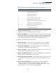

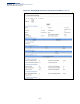
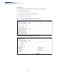
Table Of Contents
- How to Use This Guide
- Contents
- Figures
- Tables
- Getting Started
- Introduction
- Key Features
- Description of Software Features
- Configuration Backup and Restore
- Authentication
- Access Control Lists
- Port Configuration
- Rate Limiting
- Port Mirroring
- Port Trunking
- Storm Control
- Static MAC Addresses
- IP Address Filtering
- IEEE 802.1D Bridge
- Store-and-Forward Switching
- Spanning Tree Algorithm
- Virtual LANs
- IEEE 802.1Q Tunneling (QinQ)
- Traffic Prioritization
- Quality of Service
- IP Routing
- Address Resolution Protocol
- Multicast Filtering
- Link Layer Discovery Protocol
- System Defaults
- Introduction
- Web Configuration
- Using the Web Interface
- Basic Management Tasks
- Displaying System Information
- Displaying Hardware/Software Versions
- Configuring Support for Jumbo Frames
- Displaying Bridge Extension Capabilities
- Managing System Files
- Setting the System Clock
- Configuring the Console Port
- Configuring Telnet Settings
- Displaying CPU Utilization
- Configuring CPU Guard
- Displaying Memory Utilization
- Resetting the System
- Using Cloud Management
- Interface Configuration
- VLAN Configuration
- Address Table Settings
- Spanning Tree Algorithm
- Congestion Control
- Class of Service
- Quality of Service
- VoIP Traffic Configuration
- Security Measures
- AAA (Authentication, Authorization and Accounting)
- Configuring User Accounts
- Web Authentication
- Network Access (MAC Address Authentication)
- Configuring HTTPS
- Configuring the Secure Shell
- Access Control Lists
- Filtering IP Addresses for Management Access
- Configuring Port Security
- Configuring 802.1X Port Authentication
- DoS Protection
- DHCP Snooping
- IPv4 Source Guard
- ARP Inspection
- Basic Administration Protocols
- Configuring Event Logging
- Link Layer Discovery Protocol
- Power over Ethernet
- Simple Network Management Protocol
- Configuring Global Settings for SNMP
- Setting the Local Engine ID
- Specifying a Remote Engine ID
- Setting SNMPv3 Views
- Configuring SNMPv3 Groups
- Setting Community Access Strings
- Configuring Local SNMPv3 Users
- Configuring Remote SNMPv3 Users
- Specifying Trap Managers
- Creating SNMP Notification Logs
- Showing SNMP Statistics
- Remote Monitoring
- Switch Clustering
- Setting a Time Range
- LBD Configuration
- Smart Pair Configuration
- Multicast Filtering
- Overview
- Layer 2 IGMP (Snooping and Query for IPv4)
- Configuring IGMP Snooping and Query Parameters
- Specifying Static Interfaces for a Multicast Router
- Assigning Interfaces to Multicast Services
- Setting IGMP Snooping Status per Interface
- Filtering IGMP Query Packets and Multicast Data
- Displaying Multicast Groups Discovered by IGMP Snooping
- Displaying IGMP Snooping Statistics
- Filtering and Throttling IGMP Groups
- MLD Snooping (Snooping and Query for IPv6)
- Filtering and Throttling MLD Groups
- Filtering MLD Query Packets on an Interface
- IP Tools
- IP Configuration
- General IP Routing
- Unicast Routing
- Overview
- Configuring the Routing Information Protocol
- Configuring General Protocol Settings
- Clearing Entries from the Routing Table
- Specifying Network Interfaces
- Specifying Passive Interfaces
- Specifying Static Neighbors
- Configuring Route Redistribution
- Specifying an Administrative Distance
- Configuring Network Interfaces for RIP
- Displaying RIP Interface Settings
- Displaying Peer Router Information
- Resetting RIP Statistics
- IP Services
- Appendices
- Glossary

Chapter 13
| Basic Administration Protocols
Power over Ethernet
– 360 –
Default: 370000 milliwatts
ECS2100-28PP: 50000-740000 milliwatts with external power supply,
Default: 740000 milliwatts)
◆ System Operation Status – Status of the PoE power service provided to the
switch ports.
◆ PoE Power Consumption – The amount of power being consumed by PoE
devices connected to the switch.
◆ Software Version – The version of software running on the PoE controller
subsystem in the switch.
◆ Compatible Mode – Allows the switch to detect and provide power to
powered devices that were designed prior to the IEEE 802.3af PoE standard.
(Default: Disabled)
The switch automatically detects attached PoE devices by periodically
transmitting test voltages that over the Gigabit Ethernet copper-media ports.
When an IEEE 802.3af or 802.3at compatible device is plugged into one of these
ports, the powered device reflects the test voltage back to the switch, which
may then turn on the power to this device. When the compatibility mode is
enabled, this switch can detect IEEE 802.3af or 802.3at compliant devices and
the more recent 802.3af non-compliant devices that also reflect the test
voltages back to the switch. It cannot detect other legacy devices that do not
reflect back the test voltages.
For legacy devices to be supported by this switch, they must be able to accept
power over the data pairs connected to the RJ-45 ports.
◆ Maximum Allocation Mode – Sets the maximum power allocation mode
based on PD (powered device) class or user configuration. (Default: Class)
■
Class – Power allocation is based on device classification.
The IEEE standard does not define the maximum power of each PD class.
The following table is an example from Microsem's PoE IC implementation.
■
User – Power allocation is based on user configuration as defined in the
PoE Maximum Allocation Power setting on this page or as defined on the
Administration > PoE > PSE (Configure Interface) page.
Table 23: Maximum PoE Based on PD Classification
PD Class Maximum Power (Watts)
Class 0 (AF) 16.1
Class 0 (AT) 33.6
Class 1 4.2
Class 2 7.3
Class 3 16.1
Class 4 33.6