
Web Management Guide
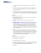
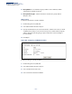
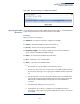
Table Of Contents
- How to Use This Guide
- Contents
- Figures
- Tables
- Getting Started
- Web Configuration
- Using the Web Interface
- Basic Management Tasks
- Displaying System Information
- Displaying Hardware/Software Versions
- Configuring Support for Jumbo Frames
- Displaying Bridge Extension Capabilities
- Managing System Files
- Setting the System Clock
- Configuring The Console Port
- Configuring Telnet Settings
- Displaying CPU Utilization
- Displaying Memory Utilization
- Resetting the System
- Interface Configuration
- VLAN Configuration
- Address Table Settings
- Spanning Tree Algorithm
- Congestion Control
- Class of Service
- Layer 2 Queue Settings
- Layer 3/4 Priority Settings
- Setting Priority Processing to IP Precedence/DSCP or CoS
- Mapping Ingress DSCP Values to Internal DSCP Values
- Mapping CoS Priorities to Internal DSCP Values
- Mapping Internal DSCP Values to Egress CoS Values
- Mapping IP Precedence Values to Internal DSCP Values
- Mapping IP Port Priority to Internal DSCP Values
- Quality of Service
- Security Measures
- AAA Authentication, Authorization and Accounting
- Configuring User Accounts
- Web Authentication
- Network Access (MAC Address Authentication)
- Configuring HTTPS
- Configuring the Secure Shell
- Access Control Lists
- Showing TCAM Utilization
- Setting the ACL Name and Type
- Configuring a Standard IPv4 ACL
- Configuring an Extended IPv4 ACL
- Configuring a Standard IPv6 ACL
- Configuring an Extended IPv6 ACL
- Configuring a MAC ACL
- Configuring an ARP ACL
- Binding a Port to an Access Control List
- Configuring ACL Mirroring
- Showing ACL Hardware Counters
- ARP Inspection
- Filtering IP Addresses for Management Access
- Configuring Port Security
- Configuring 802.1X Port Authentication
- IPv4 Source Guard
- IPv6 Source Guard
- DHCP Snooping
- Basic Administration Protocols
- Configuring Event Logging
- Link Layer Discovery Protocol
- Simple Network Management Protocol
- Configuring Global Settings for SNMP
- Setting the Local Engine ID
- Specifying a Remote Engine ID
- Setting SNMPv3 Views
- Configuring SNMPv3 Groups
- Setting Community Access Strings
- Configuring Local SNMPv3 Users
- Configuring Remote SNMPv3 Users
- Specifying Trap Managers
- Creating SNMP Notification Logs
- Showing SNMP Statistics
- Remote Monitoring
- Connectivity Fault Management
- Configuring Global Settings for CFM
- Configuring Interfaces for CFM
- Configuring CFM Maintenance Domains
- Configuring CFM Maintenance Associations
- Configuring Maintenance End Points
- Configuring Remote Maintenance End Points
- Transmitting Link Trace Messages
- Transmitting Loop Back Messages
- Transmitting Delay- Measure Requests
- Displaying Local MEPs
- Displaying Details for Local MEPs
- Displaying Local MIPs
- Displaying Remote MEPs
- Displaying Details for Remote MEPs
- Displaying the Link Trace Cache
- Displaying Fault Notification Settings
- Displaying Continuity Check Errors
- UDLD Configuration
- Multicast Filtering
- Overview
- IGMP Protocol
- Layer 2 IGMP (Snooping and Query for IPv4)
- Configuring IGMP Snooping and Query Parameters
- Specifying Static Interfaces for an IPv4 Multicast Router
- Assigning Interfaces to IPv4 Multicast Services
- Setting IGMP Snooping Status per Interface
- Filtering IGMP Query Packets
- Displaying Multicast Groups Discovered by IGMP Snooping
- Displaying IGMP Snooping Statistics
- Filtering and Throttling IGMP Groups
- MLD Snooping (Snooping and Query for IPv6)
- Layer 3 IGMP (Query used with Multicast Routing)
- IP Configuration
- IP Services
- General IP Routing
- Unicast Routing
- Overview
- Configuring the Routing Information Protocol
- Configuring General Protocol Settings
- Clearing Entries from the Routing Table
- Specifying Network Interfaces
- Specifying Passive Interfaces
- Specifying Static Neighbors
- Configuring Route Redistribution
- Specifying an Administrative Distance
- Configuring Network Interfaces for RIP
- Displaying RIP Interface Settings
- Displaying Peer Router Information
- Resetting RIP Statistics
- Configuring the Open Shortest Path First Protocol (Version 2)
- Defining Network Areas Based on Addresses
- Configuring General Protocol Settings
- Displaying Administrative Settings and Statistics
- Adding an NSSA or Stub
- Configuring NSSA Settings
- Configuring Stub Settings
- Displaying Information on NSSA and Stub Areas
- Configuring Area Ranges (Route Summarization for ABRs)
- Redistributing External Routes
- Configuring Summary Addresses (for External AS Routes)
- Configuring OSPF Interfaces
- Configuring Virtual Links
- Displaying Link State Database Information
- Displaying Information on Neighboring Routers
- Specifying Passive Interfaces
- Multicast Routing
- Appendices
- Glossary
- Index

Chapter 19
| Multicast Routing
Configuring PIMv6 for IPv6
– 632 –
it accepts the bootstrap message and forwards it. Otherwise, it drops the
message.
◆
This router will continue to be the BSR until it receives a bootstrap message
from another candidate with a higher priority (or a higher IP address if the
priorities are the same).
◆
To improve failover recovery, it is advisable to select at least two core routers in
diverse locations, each to serve as both a candidate BSR and candidate RP. It is
also preferable to set up one of these routers as both the primary BSR and RP.
Parameters
These parameters are displayed:
◆
BSR Candidate Status
– Configures the switch as a Bootstrap Router (BSR)
candidate. (Default: Disabled)
◆
VLAN ID
– Identifier of configured VLAN interface. (Range: 1-4093)
◆
Hash Mask Length
– Hash mask length (in bits) used for RP selection (see
“Configuring a PIM6 Static Rendezvous Point” on page 633 and “Configuring a
PIM6 RP Candidate” on page 635). The portion of the hash specified by the
mask length is ANDed with the group address. Therefore, when the hash
function is executed on any BSR, all groups with the same seed hash will be
mapped to the same RP. If the mask length is less than 32, then only the first
portion of the hash is used, and a single RP will be defined for multiple groups.
(Range: 0-32; Default: 10)
◆
Priority
– Priority used by the candidate bootstrap router in the election
process. The BSR candidate with the largest priority is preferred. If the priority
values are the same, the candidate with the larger IP address is elected to be
the BSR. Setting the priority to zero means that this router is not eligible to
server as the BSR. At least one router in the PIM6-SM domain must be set to a
value greater than zero. (Range: 0-255; Default: 0)
Web Interface
To configure the switch as a BSR candidate:
1.
Click Routing Protocol, PIM6, SM.
2.
Select BSR Candidate from the Step list.
3.
Specify the VLAN interface for which this router is bidding to become the BSR,
the hash mask length that will subsequently be used for RP selection if this
router is selected as the BSR, and the priority for BSR selection.
4.
Click Apply.