
Web Management Guide
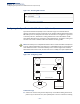
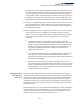
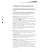
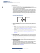
Table Of Contents
- How to Use This Guide
- Contents
- Figures
- Tables
- Getting Started
- Web Configuration
- Using the Web Interface
- Basic Management Tasks
- Displaying System Information
- Displaying Hardware/Software Versions
- Configuring Support for Jumbo Frames
- Displaying Bridge Extension Capabilities
- Managing System Files
- Setting the System Clock
- Configuring The Console Port
- Configuring Telnet Settings
- Displaying CPU Utilization
- Displaying Memory Utilization
- Resetting the System
- Interface Configuration
- VLAN Configuration
- Address Table Settings
- Spanning Tree Algorithm
- Congestion Control
- Class of Service
- Layer 2 Queue Settings
- Layer 3/4 Priority Settings
- Setting Priority Processing to IP Precedence/DSCP or CoS
- Mapping Ingress DSCP Values to Internal DSCP Values
- Mapping CoS Priorities to Internal DSCP Values
- Mapping Internal DSCP Values to Egress CoS Values
- Mapping IP Precedence Values to Internal DSCP Values
- Mapping IP Port Priority to Internal DSCP Values
- Quality of Service
- Security Measures
- AAA Authentication, Authorization and Accounting
- Configuring User Accounts
- Web Authentication
- Network Access (MAC Address Authentication)
- Configuring HTTPS
- Configuring the Secure Shell
- Access Control Lists
- Showing TCAM Utilization
- Setting the ACL Name and Type
- Configuring a Standard IPv4 ACL
- Configuring an Extended IPv4 ACL
- Configuring a Standard IPv6 ACL
- Configuring an Extended IPv6 ACL
- Configuring a MAC ACL
- Configuring an ARP ACL
- Binding a Port to an Access Control List
- Configuring ACL Mirroring
- Showing ACL Hardware Counters
- ARP Inspection
- Filtering IP Addresses for Management Access
- Configuring Port Security
- Configuring 802.1X Port Authentication
- IPv4 Source Guard
- IPv6 Source Guard
- DHCP Snooping
- Basic Administration Protocols
- Configuring Event Logging
- Link Layer Discovery Protocol
- Simple Network Management Protocol
- Configuring Global Settings for SNMP
- Setting the Local Engine ID
- Specifying a Remote Engine ID
- Setting SNMPv3 Views
- Configuring SNMPv3 Groups
- Setting Community Access Strings
- Configuring Local SNMPv3 Users
- Configuring Remote SNMPv3 Users
- Specifying Trap Managers
- Creating SNMP Notification Logs
- Showing SNMP Statistics
- Remote Monitoring
- Connectivity Fault Management
- Configuring Global Settings for CFM
- Configuring Interfaces for CFM
- Configuring CFM Maintenance Domains
- Configuring CFM Maintenance Associations
- Configuring Maintenance End Points
- Configuring Remote Maintenance End Points
- Transmitting Link Trace Messages
- Transmitting Loop Back Messages
- Transmitting Delay- Measure Requests
- Displaying Local MEPs
- Displaying Details for Local MEPs
- Displaying Local MIPs
- Displaying Remote MEPs
- Displaying Details for Remote MEPs
- Displaying the Link Trace Cache
- Displaying Fault Notification Settings
- Displaying Continuity Check Errors
- UDLD Configuration
- Multicast Filtering
- Overview
- IGMP Protocol
- Layer 2 IGMP (Snooping and Query for IPv4)
- Configuring IGMP Snooping and Query Parameters
- Specifying Static Interfaces for an IPv4 Multicast Router
- Assigning Interfaces to IPv4 Multicast Services
- Setting IGMP Snooping Status per Interface
- Filtering IGMP Query Packets
- Displaying Multicast Groups Discovered by IGMP Snooping
- Displaying IGMP Snooping Statistics
- Filtering and Throttling IGMP Groups
- MLD Snooping (Snooping and Query for IPv6)
- Layer 3 IGMP (Query used with Multicast Routing)
- IP Configuration
- IP Services
- General IP Routing
- Unicast Routing
- Overview
- Configuring the Routing Information Protocol
- Configuring General Protocol Settings
- Clearing Entries from the Routing Table
- Specifying Network Interfaces
- Specifying Passive Interfaces
- Specifying Static Neighbors
- Configuring Route Redistribution
- Specifying an Administrative Distance
- Configuring Network Interfaces for RIP
- Displaying RIP Interface Settings
- Displaying Peer Router Information
- Resetting RIP Statistics
- Configuring the Open Shortest Path First Protocol (Version 2)
- Defining Network Areas Based on Addresses
- Configuring General Protocol Settings
- Displaying Administrative Settings and Statistics
- Adding an NSSA or Stub
- Configuring NSSA Settings
- Configuring Stub Settings
- Displaying Information on NSSA and Stub Areas
- Configuring Area Ranges (Route Summarization for ABRs)
- Redistributing External Routes
- Configuring Summary Addresses (for External AS Routes)
- Configuring OSPF Interfaces
- Configuring Virtual Links
- Displaying Link State Database Information
- Displaying Information on Neighboring Routers
- Specifying Passive Interfaces
- Multicast Routing
- Appendices
- Glossary
- Index

Chapter 18
| Unicast Routing
Configuring the Open Shortest Path First Protocol (Version 2)
– 564 –
Routers in a normal area may import or export routing information about
individual nodes. To reduce the amount of routing traffic flooded onto the network,
an area can be configured to export a single summarized route that covers a broad
range of network addresses within the area (page 578). To further reduce the
amount of routes passed between areas, an area can be configured as a stub
(page 571, page 575) or a not-so-stubby area (page 571, page 572).
Normal Area – A large OSPF domain should be broken up into several areas to
increase network stability and reduce the amount of routing traffic required
through the use of route summaries that aggregate a range of addresses into a
single route. The backbone or any normal area can pass traffic between other areas,
and are therefore known as transit areas. Each router in an area has identical
routing tables. These tables may include area links, summarized links, or external
links that depict the topology of the autonomous system.
Figure 373: OSPF Areas
Command Usage
◆
Specify an Area ID and the corresponding network address range for each OSPF
broadcast area. Each area identifies a logical group of OSPF routers that actively
exchange Link State Advertisements (LSAs) to ensure that they share an
identical view of the network topology.
◆
Each area must be connected to a backbone area. This area passes routing
information between other areas in the autonomous system. All routers must
be connected to the backbone, either directly, or through a virtual link if a
direct physical connection is not possible.
◆
All areas are created as normal transit areas using the Network Area (Add) page.
A normal area (or transit area) can send and receive external LSAs. If necessary,
an area can be configured as a not-so-stubby area (NSSA) that can import
external route information into its area, or as a stubby area that cannot send or
receive external LSAs.
◆
An area must be assigned a range of subnetwork addresses. This area and the
corresponding address range forms a routing interface, and can be configured
to aggregate LSAs from all of its subnetwork addresses and exchange this
information with other routers in the network as described under “Configuring
Area Ranges (Route Summarization for ABRs)” on page 578.
backbone
area
ABR
area
ABR