
Web Management Guide
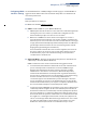

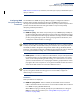
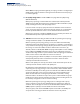
Table Of Contents
- How to Use This Guide
- Contents
- Figures
- Tables
- Getting Started
- Web Configuration
- Using the Web Interface
- Basic Management Tasks
- Displaying System Information
- Displaying Hardware/Software Versions
- Configuring Support for Jumbo Frames
- Displaying Bridge Extension Capabilities
- Managing System Files
- Setting the System Clock
- Configuring The Console Port
- Configuring Telnet Settings
- Displaying CPU Utilization
- Displaying Memory Utilization
- Resetting the System
- Interface Configuration
- VLAN Configuration
- Address Table Settings
- Spanning Tree Algorithm
- Congestion Control
- Class of Service
- Layer 2 Queue Settings
- Layer 3/4 Priority Settings
- Setting Priority Processing to IP Precedence/DSCP or CoS
- Mapping Ingress DSCP Values to Internal DSCP Values
- Mapping CoS Priorities to Internal DSCP Values
- Mapping Internal DSCP Values to Egress CoS Values
- Mapping IP Precedence Values to Internal DSCP Values
- Mapping IP Port Priority to Internal DSCP Values
- Quality of Service
- Security Measures
- AAA Authentication, Authorization and Accounting
- Configuring User Accounts
- Web Authentication
- Network Access (MAC Address Authentication)
- Configuring HTTPS
- Configuring the Secure Shell
- Access Control Lists
- Showing TCAM Utilization
- Setting the ACL Name and Type
- Configuring a Standard IPv4 ACL
- Configuring an Extended IPv4 ACL
- Configuring a Standard IPv6 ACL
- Configuring an Extended IPv6 ACL
- Configuring a MAC ACL
- Configuring an ARP ACL
- Binding a Port to an Access Control List
- Configuring ACL Mirroring
- Showing ACL Hardware Counters
- ARP Inspection
- Filtering IP Addresses for Management Access
- Configuring Port Security
- Configuring 802.1X Port Authentication
- IPv4 Source Guard
- IPv6 Source Guard
- DHCP Snooping
- Basic Administration Protocols
- Configuring Event Logging
- Link Layer Discovery Protocol
- Simple Network Management Protocol
- Configuring Global Settings for SNMP
- Setting the Local Engine ID
- Specifying a Remote Engine ID
- Setting SNMPv3 Views
- Configuring SNMPv3 Groups
- Setting Community Access Strings
- Configuring Local SNMPv3 Users
- Configuring Remote SNMPv3 Users
- Specifying Trap Managers
- Creating SNMP Notification Logs
- Showing SNMP Statistics
- Remote Monitoring
- Connectivity Fault Management
- Configuring Global Settings for CFM
- Configuring Interfaces for CFM
- Configuring CFM Maintenance Domains
- Configuring CFM Maintenance Associations
- Configuring Maintenance End Points
- Configuring Remote Maintenance End Points
- Transmitting Link Trace Messages
- Transmitting Loop Back Messages
- Transmitting Delay- Measure Requests
- Displaying Local MEPs
- Displaying Details for Local MEPs
- Displaying Local MIPs
- Displaying Remote MEPs
- Displaying Details for Remote MEPs
- Displaying the Link Trace Cache
- Displaying Fault Notification Settings
- Displaying Continuity Check Errors
- UDLD Configuration
- Multicast Filtering
- Overview
- IGMP Protocol
- Layer 2 IGMP (Snooping and Query for IPv4)
- Configuring IGMP Snooping and Query Parameters
- Specifying Static Interfaces for an IPv4 Multicast Router
- Assigning Interfaces to IPv4 Multicast Services
- Setting IGMP Snooping Status per Interface
- Filtering IGMP Query Packets
- Displaying Multicast Groups Discovered by IGMP Snooping
- Displaying IGMP Snooping Statistics
- Filtering and Throttling IGMP Groups
- MLD Snooping (Snooping and Query for IPv6)
- Layer 3 IGMP (Query used with Multicast Routing)
- IP Configuration
- IP Services
- General IP Routing
- Unicast Routing
- Overview
- Configuring the Routing Information Protocol
- Configuring General Protocol Settings
- Clearing Entries from the Routing Table
- Specifying Network Interfaces
- Specifying Passive Interfaces
- Specifying Static Neighbors
- Configuring Route Redistribution
- Specifying an Administrative Distance
- Configuring Network Interfaces for RIP
- Displaying RIP Interface Settings
- Displaying Peer Router Information
- Resetting RIP Statistics
- Configuring the Open Shortest Path First Protocol (Version 2)
- Defining Network Areas Based on Addresses
- Configuring General Protocol Settings
- Displaying Administrative Settings and Statistics
- Adding an NSSA or Stub
- Configuring NSSA Settings
- Configuring Stub Settings
- Displaying Information on NSSA and Stub Areas
- Configuring Area Ranges (Route Summarization for ABRs)
- Redistributing External Routes
- Configuring Summary Addresses (for External AS Routes)
- Configuring OSPF Interfaces
- Configuring Virtual Links
- Displaying Link State Database Information
- Displaying Information on Neighboring Routers
- Specifying Passive Interfaces
- Multicast Routing
- Appendices
- Glossary
- Index

Chapter 12
| Basic Administration Protocols
UDLD Configuration
– 430 –
scenarios (typically only on point-to-point links where no communication
failure between two neighbors is admissible).
◆
Operation State
– Shows the UDLD operational state (Disabled, Link down,
Link up, Advertisement, Detection, Disabled port, Advertisement - Single
neighbor, Advertisement - Multiple neighbors)
◆
Port State
– Shows the UDLD port state (Unknown, Bidirectional,
Unidirectional, Transmit-to-receive loop, Mismatch with neighbor state
reported, Neighbor's echo is empty)
The state is Unknown if the link is down or not connected to a UDLD-capable
device. The state is Bidirectional if the link has a normal two-way connection to
a UDLD-capable device. All other states indicate mis-wiring.
◆
Message Interval
– The interval between UDLD probe messages used for the
indicated operational state.
◆
Detection Interval
– The period the switch remains in detection state after
discovering a neighbor.
Web Interface
To enable UDLD and aggressive mode:
1.
Click Administration, UDLD, Configure Interface.
2.
Enable UDLD and aggressive mode on the required ports.
3.
Click Apply.
Figure 268: Configuring UDLD Interface Settings
Displaying
UDLD Neighbor
Information
Use the Administration > UDLD (Show Information) page to show UDLD neighbor
information, including neighbor state, expiration time, and protocol intervals.
Parameters
These parameters are displayed:
◆
Port
– Port identifier. (Range: 1-32/54)