
Web Management Guide
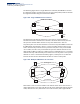
Table Of Contents
- How to Use This Guide
- Contents
- Figures
- Tables
- Getting Started
- Web Configuration
- Using the Web Interface
- Basic Management Tasks
- Displaying System Information
- Displaying Hardware/Software Versions
- Configuring Support for Jumbo Frames
- Displaying Bridge Extension Capabilities
- Managing System Files
- Setting the System Clock
- Configuring The Console Port
- Configuring Telnet Settings
- Displaying CPU Utilization
- Displaying Memory Utilization
- Resetting the System
- Interface Configuration
- VLAN Configuration
- Address Table Settings
- Spanning Tree Algorithm
- Congestion Control
- Class of Service
- Layer 2 Queue Settings
- Layer 3/4 Priority Settings
- Setting Priority Processing to IP Precedence/DSCP or CoS
- Mapping Ingress DSCP Values to Internal DSCP Values
- Mapping CoS Priorities to Internal DSCP Values
- Mapping Internal DSCP Values to Egress CoS Values
- Mapping IP Precedence Values to Internal DSCP Values
- Mapping IP Port Priority to Internal DSCP Values
- Quality of Service
- Security Measures
- AAA Authentication, Authorization and Accounting
- Configuring User Accounts
- Web Authentication
- Network Access (MAC Address Authentication)
- Configuring HTTPS
- Configuring the Secure Shell
- Access Control Lists
- Showing TCAM Utilization
- Setting the ACL Name and Type
- Configuring a Standard IPv4 ACL
- Configuring an Extended IPv4 ACL
- Configuring a Standard IPv6 ACL
- Configuring an Extended IPv6 ACL
- Configuring a MAC ACL
- Configuring an ARP ACL
- Binding a Port to an Access Control List
- Configuring ACL Mirroring
- Showing ACL Hardware Counters
- ARP Inspection
- Filtering IP Addresses for Management Access
- Configuring Port Security
- Configuring 802.1X Port Authentication
- IPv4 Source Guard
- IPv6 Source Guard
- DHCP Snooping
- Basic Administration Protocols
- Configuring Event Logging
- Link Layer Discovery Protocol
- Simple Network Management Protocol
- Configuring Global Settings for SNMP
- Setting the Local Engine ID
- Specifying a Remote Engine ID
- Setting SNMPv3 Views
- Configuring SNMPv3 Groups
- Setting Community Access Strings
- Configuring Local SNMPv3 Users
- Configuring Remote SNMPv3 Users
- Specifying Trap Managers
- Creating SNMP Notification Logs
- Showing SNMP Statistics
- Remote Monitoring
- Connectivity Fault Management
- Configuring Global Settings for CFM
- Configuring Interfaces for CFM
- Configuring CFM Maintenance Domains
- Configuring CFM Maintenance Associations
- Configuring Maintenance End Points
- Configuring Remote Maintenance End Points
- Transmitting Link Trace Messages
- Transmitting Loop Back Messages
- Transmitting Delay- Measure Requests
- Displaying Local MEPs
- Displaying Details for Local MEPs
- Displaying Local MIPs
- Displaying Remote MEPs
- Displaying Details for Remote MEPs
- Displaying the Link Trace Cache
- Displaying Fault Notification Settings
- Displaying Continuity Check Errors
- UDLD Configuration
- Multicast Filtering
- Overview
- IGMP Protocol
- Layer 2 IGMP (Snooping and Query for IPv4)
- Configuring IGMP Snooping and Query Parameters
- Specifying Static Interfaces for an IPv4 Multicast Router
- Assigning Interfaces to IPv4 Multicast Services
- Setting IGMP Snooping Status per Interface
- Filtering IGMP Query Packets
- Displaying Multicast Groups Discovered by IGMP Snooping
- Displaying IGMP Snooping Statistics
- Filtering and Throttling IGMP Groups
- MLD Snooping (Snooping and Query for IPv6)
- Layer 3 IGMP (Query used with Multicast Routing)
- IP Configuration
- IP Services
- General IP Routing
- Unicast Routing
- Overview
- Configuring the Routing Information Protocol
- Configuring General Protocol Settings
- Clearing Entries from the Routing Table
- Specifying Network Interfaces
- Specifying Passive Interfaces
- Specifying Static Neighbors
- Configuring Route Redistribution
- Specifying an Administrative Distance
- Configuring Network Interfaces for RIP
- Displaying RIP Interface Settings
- Displaying Peer Router Information
- Resetting RIP Statistics
- Configuring the Open Shortest Path First Protocol (Version 2)
- Defining Network Areas Based on Addresses
- Configuring General Protocol Settings
- Displaying Administrative Settings and Statistics
- Adding an NSSA or Stub
- Configuring NSSA Settings
- Configuring Stub Settings
- Displaying Information on NSSA and Stub Areas
- Configuring Area Ranges (Route Summarization for ABRs)
- Redistributing External Routes
- Configuring Summary Addresses (for External AS Routes)
- Configuring OSPF Interfaces
- Configuring Virtual Links
- Displaying Link State Database Information
- Displaying Information on Neighboring Routers
- Specifying Passive Interfaces
- Multicast Routing
- Appendices
- Glossary
- Index

Chapter 12
| Basic Administration Protocols
Connectivity Fault Management
– 393 –
Basic CFM Operations
CFM uses standard Ethernet frames for sending protocol messages. Both the source
and destination address for these messages are based on unicast or multicast MAC
addresses, and therefore confined to a single Layer 2 CFM service VLAN. For this
reason, the transmission, forwarding, and processing of CFM frames is performed
by bridges, not routers. Bridges that do not recognize CFM messages forward them
as normal data. There are three basic types of CFM messages, including continuity
check, link trace, and loop back.
Continuity check messages (CCMs) are multicast within a single Service Instance
(i.e., a specific MA), allowing MEPs to discover other MEPs within the same MA, and
MIPs to discover MEPs. Connectivity faults are indicated when a known MEP stops
sending CCMs, or a remote MEP configured in a static list does not come up.
Configuration errors, such as a cross-connect between different MAs, are indicated
when a CCM is received with an incorrect MA identifier or maintenance level.
Loop back messages are used for fault verification. These messages can be sent
using the MAC address of any destination MEP within the same MA. If the target
MEP’s identifier has been discovered through CCM messages, then a loop back
message can also be sent using the MEPs identifier. A reply indicates that the
destination is reachable.
Link trace messages are used for fault verification. These messages are multicast
frames sent out to track the hop-by-hop path to a target MEP within the same MA.
Responses provide information on the ingress, egress, and relay action taken at
each hop along the path, providing vital information about connectivity problems.
Responses allow the sender to discover all of the maintenance points that would be
traversed by a data frame sent to the target MAC address.
SNMP traps can also be configured to provide an automated method of fault
notification. If the fault notification generator detects one or more defects within
the configured time period, and fault alarms are enabled, a corresponding trap will
be sent. No further fault alarms are sent until the fault notification generator has
been reset by the passage of a configured time period without detecting any
further faults. Upon receiving a fault alarm, you should inspect the related SNMP
objects for the reporting MEP, diagnose the fault, correct it, and re-examine the
MEP’s SNMP objects to see whether the fault notification generator has been reset.
Configuration Guidelines
1.
Configure the maintenance domains with the MD List (see "Configuring CFM
Maintenance Domains").
2.
Configure the maintenance associations with MA List (see "Configuring CFM
Maintenance Associations").
3.
Configure the local maintenance end points (MEPs) which will serve as the
domain service access points for the specified maintenance association using
the MEP List (see "Configuring CFM Maintenance Associations").