
Web Management Guide
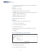

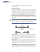
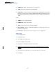
Table Of Contents
- How to Use This Guide
- Contents
- Figures
- Tables
- Getting Started
- Web Configuration
- Using the Web Interface
- Basic Management Tasks
- Displaying System Information
- Displaying Hardware/Software Versions
- Configuring Support for Jumbo Frames
- Displaying Bridge Extension Capabilities
- Managing System Files
- Setting the System Clock
- Configuring The Console Port
- Configuring Telnet Settings
- Displaying CPU Utilization
- Displaying Memory Utilization
- Resetting the System
- Interface Configuration
- VLAN Configuration
- Address Table Settings
- Spanning Tree Algorithm
- Congestion Control
- Class of Service
- Layer 2 Queue Settings
- Layer 3/4 Priority Settings
- Setting Priority Processing to IP Precedence/DSCP or CoS
- Mapping Ingress DSCP Values to Internal DSCP Values
- Mapping CoS Priorities to Internal DSCP Values
- Mapping Internal DSCP Values to Egress CoS Values
- Mapping IP Precedence Values to Internal DSCP Values
- Mapping IP Port Priority to Internal DSCP Values
- Quality of Service
- Security Measures
- AAA Authentication, Authorization and Accounting
- Configuring User Accounts
- Web Authentication
- Network Access (MAC Address Authentication)
- Configuring HTTPS
- Configuring the Secure Shell
- Access Control Lists
- Showing TCAM Utilization
- Setting the ACL Name and Type
- Configuring a Standard IPv4 ACL
- Configuring an Extended IPv4 ACL
- Configuring a Standard IPv6 ACL
- Configuring an Extended IPv6 ACL
- Configuring a MAC ACL
- Configuring an ARP ACL
- Binding a Port to an Access Control List
- Configuring ACL Mirroring
- Showing ACL Hardware Counters
- ARP Inspection
- Filtering IP Addresses for Management Access
- Configuring Port Security
- Configuring 802.1X Port Authentication
- IPv4 Source Guard
- IPv6 Source Guard
- DHCP Snooping
- Basic Administration Protocols
- Configuring Event Logging
- Link Layer Discovery Protocol
- Simple Network Management Protocol
- Configuring Global Settings for SNMP
- Setting the Local Engine ID
- Specifying a Remote Engine ID
- Setting SNMPv3 Views
- Configuring SNMPv3 Groups
- Setting Community Access Strings
- Configuring Local SNMPv3 Users
- Configuring Remote SNMPv3 Users
- Specifying Trap Managers
- Creating SNMP Notification Logs
- Showing SNMP Statistics
- Remote Monitoring
- Connectivity Fault Management
- Configuring Global Settings for CFM
- Configuring Interfaces for CFM
- Configuring CFM Maintenance Domains
- Configuring CFM Maintenance Associations
- Configuring Maintenance End Points
- Configuring Remote Maintenance End Points
- Transmitting Link Trace Messages
- Transmitting Loop Back Messages
- Transmitting Delay- Measure Requests
- Displaying Local MEPs
- Displaying Details for Local MEPs
- Displaying Local MIPs
- Displaying Remote MEPs
- Displaying Details for Remote MEPs
- Displaying the Link Trace Cache
- Displaying Fault Notification Settings
- Displaying Continuity Check Errors
- UDLD Configuration
- Multicast Filtering
- Overview
- IGMP Protocol
- Layer 2 IGMP (Snooping and Query for IPv4)
- Configuring IGMP Snooping and Query Parameters
- Specifying Static Interfaces for an IPv4 Multicast Router
- Assigning Interfaces to IPv4 Multicast Services
- Setting IGMP Snooping Status per Interface
- Filtering IGMP Query Packets
- Displaying Multicast Groups Discovered by IGMP Snooping
- Displaying IGMP Snooping Statistics
- Filtering and Throttling IGMP Groups
- MLD Snooping (Snooping and Query for IPv6)
- Layer 3 IGMP (Query used with Multicast Routing)
- IP Configuration
- IP Services
- General IP Routing
- Unicast Routing
- Overview
- Configuring the Routing Information Protocol
- Configuring General Protocol Settings
- Clearing Entries from the Routing Table
- Specifying Network Interfaces
- Specifying Passive Interfaces
- Specifying Static Neighbors
- Configuring Route Redistribution
- Specifying an Administrative Distance
- Configuring Network Interfaces for RIP
- Displaying RIP Interface Settings
- Displaying Peer Router Information
- Resetting RIP Statistics
- Configuring the Open Shortest Path First Protocol (Version 2)
- Defining Network Areas Based on Addresses
- Configuring General Protocol Settings
- Displaying Administrative Settings and Statistics
- Adding an NSSA or Stub
- Configuring NSSA Settings
- Configuring Stub Settings
- Displaying Information on NSSA and Stub Areas
- Configuring Area Ranges (Route Summarization for ABRs)
- Redistributing External Routes
- Configuring Summary Addresses (for External AS Routes)
- Configuring OSPF Interfaces
- Configuring Virtual Links
- Displaying Link State Database Information
- Displaying Information on Neighboring Routers
- Specifying Passive Interfaces
- Multicast Routing
- Appendices
- Glossary
- Index

Chapter 5
| VLAN Configuration
IEEE 802.1Q VLANs
– 146 –
◆
Passing traffic between VLAN-aware and VLAN-unaware devices
◆
Priority tagging
Assigning Ports to VLANs
Before enabling VLANs for the switch, you must first assign each port to the VLAN
group(s) in which it will participate. By default all ports are assigned to VLAN 1 as
untagged ports. Add a port as a tagged port if you want it to carry traffic for one or
more VLANs, and any intermediate network devices or the host at the other end of
the connection supports VLANs. Then manually assign ports on the other VLAN-
aware network devices along the path that will carry this traffic to the same
VLAN(s). However, if you want a port on this switch to participate in one or more
VLANs, but none of the intermediate network devices nor the host at the other end
of the connection supports VLANs, then you should add this port to the VLAN as an
untagged port.
Note:
VLAN-tagged frames can pass through VLAN-aware or VLAN-unaware
network interconnection devices, but the VLAN tags should be stripped off before
passing it on to any end-node host that does not support VLAN tagging.
Figure 67: VLAN Compliant and VLAN Non-compliant Devices
VLAN Classification
– When the switch receives a frame, it classifies the frame in
one of two ways. If the frame is untagged, the switch assigns the frame to an
associated VLAN (based on the default VLAN ID of the receiving port). But if the
frame is tagged, the switch uses the tagged VLAN ID to identify the port broadcast
domain of the frame.
Port Overlapping
– Port overlapping can be used to allow access to commonly
shared network resources among different VLAN groups, such as file servers or
printers. Note that if you implement VLANs which do not overlap, but still need to
communicate, you can connect them by enabled routing on this switch.
Untagged VLANs
– Untagged VLANs are typically used to reduce broadcast traffic
and to increase security. A group of network users assigned to a VLAN form a
broadcast domain that is separate from other VLANs configured on the switch.
Packets are forwarded only between ports that are designated for the same VLAN.
VA
VA: VLAN Aware
VU: VLAN Unaware
VA
tagged frames
VA VUVA
tagged
frames
untagged
frames