EDGE 540 Hand-made Almost Ready to Fly R/C Model Aircraft ASSEMBLY MANUAL Specifications Wingspan---------------------------------------- 68.2 in------------------------- 173.2cm. Wing area--------------------------------------- 753sq.in-------------------- 48.6 sq.dm. Approximate flying weight-------------------- 8.4-8.8lbs--------------------- 3.8-4kg. Length-------------------------------------------- 60.6 in---------------------------- 154cm. Recommended engine size-----------------.61- .91 cu.
EDGE 540. Instruction Manual. INTRODUCTION. Thank you for choosing the EDGE 540 ARTF by SEAGULL MODELS. The EDGE 540 was designed with the intermediate/advanced sport flyer in mind. It is a semi scale airplane which is easy to fly and quick to assemble. The airframe is conventionally built using balsa, plywood to make it stronger than the average ARTF , yet the design allows the aeroplane to be kept light. You will find that most of the work has been done for you already.
EDGE 540. Instruction Manual. NOTE: To avoid scratching your new aeroplane we suggest that you cover your workbench with an old towel. Keep a couple of jars or bowls handy to hold the small parts after you open the bags. Please trial fit all parts. Make sure you have the correct parts and that they fit and are aligned properly before gluing! This will ensure proper assembly as the EDGE 540 is made from natural materials and minor adjustments may have to be made.
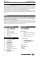
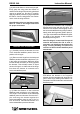
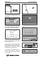
EDGE 540. Instruction Manual. HINGING THE AILERONS. Note:The control surfaces, including the ailerons, elevators, and rudder, are prehinged with hinges installed, but the hinges are not glued in place. It is imperative that you properly adhere the hinges in place per the steps that follow using a high-quality thin C/A glue. 1) Carefully remove the aileron from one of the wing panels. Note the position of the hinges. 4)Deflect the aileron and completely saturate each hinge with thin C/A glue.
EDGE 540. Instruction Manual. 8) After both ailerons are securely hinged, firmly grasp the wing panel and aileron to make sure the hinges are securely glued and cannot be pulled out. Do this by carefully applying medium pressure, trying to separate the aileron from the wing panel. Use caution not to crush the wing structure. Note:Work the aileron up and down several times to “work in” the hinges and check for proper movement. HINGING THE ELEVATORS.
EDGE 540. Instruction Manual. 6) Using C/A remover/debonder and a paper towel, remove any excess C/A glue that may have accumulated on the horizontal stabilizer or in the elevator hinge area. T-pin. 7) Repeat this process with the other horizontal stabilizer panel, securely hinging the elevator in place. Hinges. 8) After both elevator are securely hinged, firmly grasp the horizontal stabilizer panel and elevator to make sure the hinges are securely glued and cannot be pulled out.
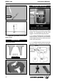
EDGE 540. Instruction Manual. Install the rubber grommets and brass collets onto the aileron servo. Test fit the servo into the aileron servo mount. Install the servo into the servo tray. C/A glue. 5) Turn the vertical fin panel over and deflect the rudder in the opposite direction from the opposite side. Apply thin C/A glue to each hinge, making sure that the C/A penetrates into the rudder and fuselage panel. Secure the servos with the screws provided with your radio system.
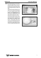
EDGE 540. Instruction Manual. Wing panel bottom. Pull. Thread. Thread. Electric wire. Electric wire. Plastic tape. Aileron electric. Install the aileron servo tray into the servo mount. Repeat the procedure for orther wing haft. AILERON LINKAGE. INSTALLING THE AILERON LINKAGE. 1) Using a ruler & pen to draw a straight line as below picture. Pen.
EDGE 540. Instruction Manual. Servo arm. Straigh line. 2) Locate the two nylon control horns, two nylon control horn backplates and two machine screws. 2mm x 30 mm. 3) Position the aileron horn on the bottom side of aileron. The clevis attachment holes should be positioned over the hinge line. 7) Pushrod assemble as same as pictures below: Control Horn. Mounting Screws. Mounting Plate. 4) Using a 1mm drill bit and the control horns as a guide, drill the mounting holes through the aileron halves.
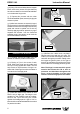
EDGE 540. Instruction Manual. INSTALLING THE BATTERY. Battery. C/A glue. FUEL TANK. INSTALLING THE STOPPER ASSEMBLY. 1) Using a modeling knife, carefully cut off the rear portion of one of the 3 nylon tubes leaving 1/2” protruding from the rear of the stopper. This will be the fuel pick up tube. Repeat the procedure for the other aileron servo. ENGINE MOUNT. See pictures below: 4mm X 20mm. 10 2) Using a modeling knife, cut one length of silicon fuel line.
EDGE 540. Instruction Manual. Vent tube. Fuel pick-up tube. Fuel fill tube. Carefully use a lighter or heat gun to permenently set the angle of the vent tube. Important: When the stopper assembly is installed in the tank, the top of the vent tube should rest just below the top surface of the tank. It should not touch the top of the tank. You should mark which tube is the vent and which is the fuel pickup when you attach fuel tubing to the tubes in the stopper.
EDGE 540. Instruction Manual. 125mm. 4mm X 30mm. 2) Place your engine onto the engine mount. Adjust the engine is centered of the edges of the engine case. 3) When you are satisfied with the alignment, mark the locations of the engine mounting. 4) Remove the engine. Using an drill bit, drill the mounting holes through the engine mount at the four locations marked. Pushrod wire. 4.2mm (4 pcs). WHEEL AND WHEEL PANTS. 5) Bolt the engine to the engine mount using the four machine screws.
EDGE 540. Instruction Manual. (2) Washer. (2) Wheel Collar. Axle. 2) Follow diagram below for wheel pant installation: Wheel. Nut. Nut. (2) Washer. Wheel Collar. Axle. Nut. Nut. Wheel. Landing Gear. Wheel Pant. Landing gear. 10mm. 3) You have to trim each axle using a toll cutting and cut-off wheel. Caution when cutting the axles and wear protective goggles. 46mm.
EDGE 540. Instruction Manual. 3mmX10mm. 4) A drop of C/A glue on the wheel collar screws will help keep them from coming lose during operation. Trim and cut. Repeat the process for the other wheel. INSTALLING THE MAIN LANDING GEAR. 1) The blind nuts for securing the landing gear are already mounted inside the fuselage. 2) Using the hardware provided, mount the main landing gear to the fuselage. Trim and cut.
EDGE 540. Instruction Manual. 3mm X 10mm (6pcs). 1.5mm wire (needle valve). INSTALLING THE SPINNER. 1) Install the spinner backplate, propeller and spinner cone. The spinner cone is held in place using two 3mm x 15mm wood screws. (spinner is not included). The propeller should not touch any part of the spinner cone. If it does, use a sharp modeling knife and carefully trim away the spinner cone where the propeller comes in contact with it.
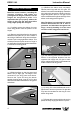
EDGE 540. Instruction Manual. ELEVATOR - RUDDER SERVO INSTALLATION. Center line. 1) Locate and cut out the covering film from the servo holes in both sides of fuselage. 2) Using a modeling knife, carefully remove the covering at mounting slot of horizontal stabilizer ( both side of fuselage). Remove covering. Remove covering. 2) Install the rubber grommets and brass collets onto the elevator and rudder servo. Test fit the servo into the aileron servo mount.
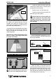
EDGE 540. Instruction Manual. Remove covering. When cutting through the covering to remove it, cut with only enough pressure to only cut through the covering itself. Cutting into the balsa structure may weaken it. 6) Using a modeling knife, carefully remove the covering that overlaps the stabilizer mounting platform sides in the fuselage. Remove the covering from both the top and the bottom of the platform sides.
EDGE 540. Instruction Manual. 5) Slide the vertical stabilizer back in place. Using a triangle, check to ensure that the vertical stabilizer is aligned 90º to the horizontal stabilizer. Horizontal Stabilizer. 3) While holding the vertical stabilizer firmly in place, use a pen and draw a line on each side of the vertical stabilizer where it meets the top of the fuselage. Pen. 4) Remove the stabilizer. Using a modeling knife, remove the covering from below the lines you drew.
EDGE 540. Instruction Manual. 2) Position the elevator horn on the both side of elevator. The clevis attach- ment holes should be positioned over the hinge line. Elevator control horn. 2mm x 20 mm. Rudder control horn. ELEVATOR-RUDDER PUSHROD INSTALLATION. Control Horn. Elevator - rudder pushrods assembly follow pictures below. 11.8cm. Rudder pushrod. Mounting Screws. Mounting Plate. Elevator pushrod. 10.8cm. 3) Using a 1.
EDGE 540. Instruction Manual. Right side. 2mm X 20mm. Control clasp. 2 screws. MOUNTING THE TAIL WHEEL BRACKET. 1) Set the tail wheel assembly in place on the plywood plate. The pivot point of the tail wheel wire should be even with the rudder hinge line and the tail wheel bracket should be centered on the plywood plate. INSTALLING TAIL STRUT SYSTEM. Tail strut system assembly follow pictures below. 2 Using a pen, mark the locations of the two mounting screws.
EDGE 540. Instruction Manual. INSTALLING THE SWITCH. 3x10mm. Install the switch into the precut hole in the servo tray, in the fuselage, from the bottom. Use the two screws provided with the switch to secure it in place. Drill two 3/32” holes through the tray for the screws to pass through. 3/ 32” Hole. Switch. INSTALLING THE FUSELAGE SERVO. Throttle servo. THROTTLE SERVO INSTALLATION. 1) Install adjustable servo connector in the servo arm.
EDGE 540. Instruction Manual. Adjustable Servo connector. Receiver. Servo arm. 2) Install the rubber grommets and brass collets onto the throttle servo. Test fit the servo into the aileron servo mount. Because the size of servos differ, you may need to adjust the size of the precut opening in the mount. The notch in the sides of the mount allow the servo lead to pass through. 3) Secure the servos with the screws provided with your radio system. Antenna tube. Antenna. 4) Install the pushrod throttle.
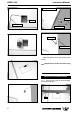
EDGE 540. Instruction Manual. ATTACHMENT WING-FUSELAGE. See picture below: Wing bolts. Remove covering. Attach the aluminium tube into fuselage. BALANCING. Insert two wing panels as pictures below: 1) It is critical that your airplane be balanced correctly. Improper balance will cause your plane to lose control and crash. The center of gravity is locate100-110mm back from the leading edge of the wing, measured at the fuselage. 2) If the nose of the plane falls, the plane is nose heavy.
EDGE 540. 2) Turn on the radio system, and with the trim tabs on the transmitter in neutral, center the control surfaces by making adjustments to the clevises or adjustable servo connectors. The servo arms should be centered also. 3) When the elevator, rudder and aileron control surfaces are centered, use a ruler and check the amount of the control throw in each surface.
EDGE 540. Instruction Manual.
EDGE 540. 26 Instruction Manual.