
Manual

Installation Instructions for Angle and Kurve Display Sign
w/2SQ Canopy
Installation Setup
1718 W. Fullerton Ave
Chicago, IL 60614
Tel: 773-770-1195
Fax: 773-935-5613
www.edgelighting.com
info@edgelighting.com
© 2013 Edge Lighting. All Rights Reserved.
SAVE THESE INSTRUCTIONS!
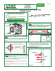
- This instruction shows a typical new construction
installation.
IMPORTANT INFORMATION
2: Measure the distance from center of each hinge to the other
hinge. Typically, the most left hinge contains the power
wires.
904-KAD-2SQ-01
A
1
KD-7WDC-2SQ-_
3: The hinge containing power cables should be aligned with
the center of the electrical box. Starting from the center
of the electrical box, mark all measured point(s) onto the
wall ensuring the marked points are leveled horizontally
with the center of the junction box.
MEASURE
CHANNEL
B
CHANNEL
HINGE
2
HINGE
AD-7WDC-2SQ-_
MEASUREMENTS
FROM STEP 1
3
3
ELECTRICAL BOX CENTER LINE
WALL
- This product is powered with a 24 volt DC power supply
such as PSB-96W-010-24VDC.
NOTE: Depending on fixture length, the fixture is provided with 2
to 4 hinges.
1
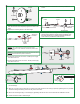
provided #8-32 screws. Install drywall and finish.
: Install 2" plaster ring to electrical box and secure with two
1:
2: Tap the anchors to the new marked holes with a hammer up
to the threaded portion
For each base, mark additional points at 0.6" to the top and
bottom of the previously marked points.
3: Screw in the threaded portion of the anchor(s) with a Phillips
screwdriver.
D
SIDE VIEW
NOTE: The base holes should be in a vertical position at 90°
angle to the direction of the fixture.
ANCHOR FOR
STANDOFF POST
WALL
0.6"
APART
2
MARKED
POINT
0.6"
APART
Install Fixture
C
2" PLASTER
PLATE
#8-32 SCREW
ELECTRICAL
BOX
NOTE: To replace the existing plaster ring, some modification of
drywall around the junction box is necessary.
3
1